The following sample configuration shows how Loop Protect functions in a basic Spanning Tree topology.
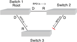
In the example in the figure below, Switch 1 is the root bridge with BPDUs being sent to both Switch 2 and 3. (Designated ports are labeled D and root ports are labeled R.) Switch 3 has placed the port that connects to Switch 2 in a blocking state.
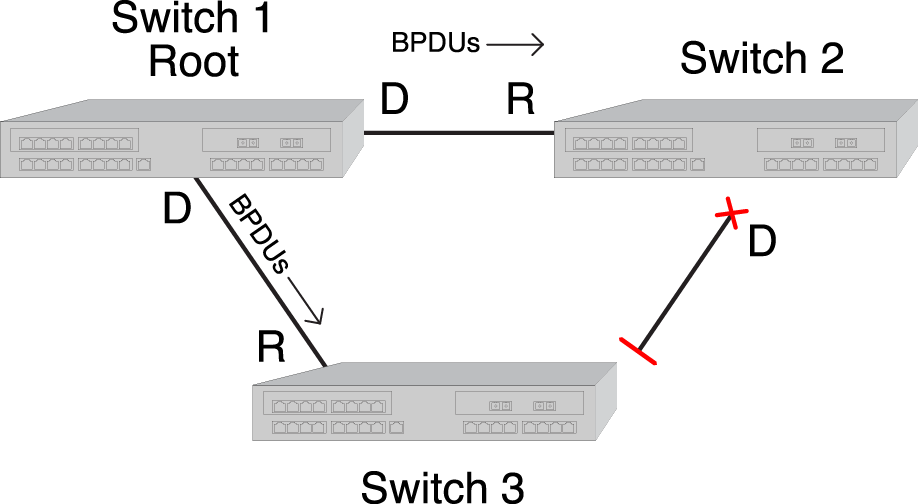
The figure below shows that, without Loop Protect, a failure could be as simple as someone accidentally disabling Spanning Tree on the port between Switch 2 and 3. Switch 3‘s blocking port eventually transitions to a forwarding state which leads to a looped condition.
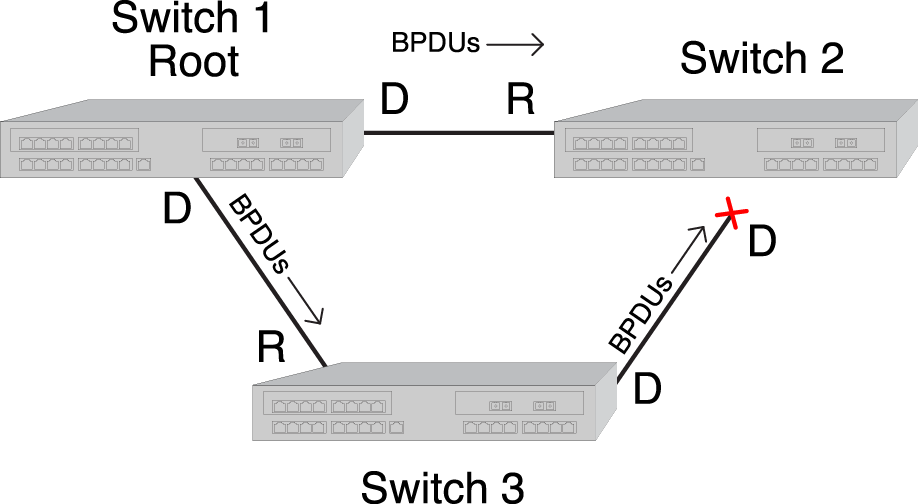
The figure below shows that, with Loop Protect enabled, Switch 3 will not go to a forwarding state until it has received a BPDU from Switch 2.
 Print
this page
Print
this page Email this topic
 Feedback
 View PDF
 Download EPUB