This section provides an overview of the LSNAT components.
The LSNAT configuration is made up of one or more server farms, each containing multiple real servers that face the client through a configured virtual server. All aspects of an LSNAT configuration relate to the configuration or management of one of these three LSNAT components: server farm, real server, and virtual server. LSNAT components are accessible over any combination of VLAN, L3 tunnel, and L2 tunnel interfaces.
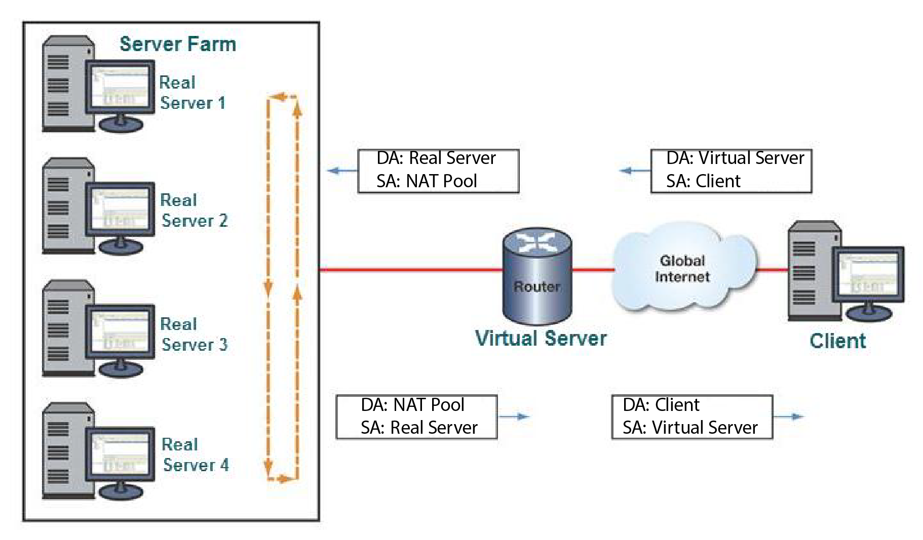
LSNAT Packet Flow presents a generic LSNAT packet flow. The actual IP address type depends upon the client and real server IP address configurations. In any case, the client and virtual server IP address type must agree, and the NAT pool and server farm address type must agree.
A request for services is sent by the client to the Virtual server IP address (VIP) on the LSNAT configured router. The source address for this request is the client IP address. The destination address for the request is the LSNAT virtual server (VIP) address. The LSNAT router recognizes the VIP address and based upon the server load balancing algorithm (round robin is displayed) LSNAT changes the destination address from the VIP address to the address of one of the real server members of the server farm associated with the VIP address. The packet is forwarded to the selected real server with a source address taken from the configured source NAT pool and the real server as the destination address.
When the real server sends a response back to the client, LSNAT sees the real server address and translates it back to the virtual server before forwarding the packet on to the client.
 Print
this page
Print
this page Email this topic
 Feedback
 View PDF
 Download EPUB