It is unlikely that you will run out of LAG resources for most link aggregation configurations, but it is possible. See Extreme Networks Platform LAG Support for a listing of LAG support for your system. Should you run out of LAG resources, excess aggregatable ports are placed in standby mode.
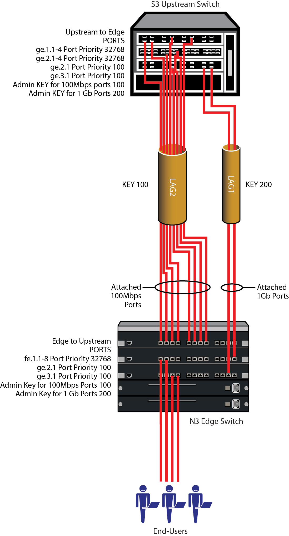
Making use of the port priority parameter, this example shows how you can ensure the order in which aggregatable ports form a LAG and are moved to the attached state. In configuration example 2, two uplink LAGs will be manually configured between two edge switch chassis. The first LAG consists of two 1 Gb ports. The second LAG consists of eight 100 Mbps ports. In this example we will ensure that the two 1Gb port LAG forms before the eight 100 Mbps port LAG.
See Example 2 Configuration for an illustration of this example, including port, key and port priority assignments.
The LAG configuration will ensure that the two 1Gb ports attach to the first available LAG (LAG1). The eight 100Mbps ports will then attach to the second available LAG (LAG2)
Which device determines port selection for the LAG is an optional consideration. For this example, system priorities are not modified, the lowest MAC address device will determine port selection for the LAG.
There are two physical port speeds in our example, 100Mbps and 1Gb. A LAG only moves ports of the same speed to the attached state. Selecting the ports to move to attached state is based upon the lowest port priority. If port priorities are the same, the lowest port number breaks the tie. For our example, we want to ensure that the 1Gb ports are moved to the attached state for LAG1. Port priority for 1Gb ports is set to 100. Port priority for 100Mbps ports is left at the default value of 32768.
The admin key for each 100 Mbps to 1Gb physical port link and LAG in the example is set to 100, and for each 1Gb to 1Gb physical port link and LAG is set to 200. This ensures that LAGs will form for each set of ports.
For this example we will allow single port LAGs to form. The single port LAG feature will be set to enabled for both devices.
Flow regeneration (S-, K-Series) is enabled for both devices in our example. This setting will ensure that should a LAG port drop out and then become active again, LACP will redistribute existing flows over all the ports in the new LAG.
The output algorithm defaults to selecting the output port based upon the destination and source IP address. This setting will not be changed in our example.
 Print
this page
Print
this page Email this topic
 Feedback
 View PDF
 Download EPUB