Inside the MST region, a wholly contained set of topologies is maintained separate from the outside world. For example, MSTI 1 in MST region A has no correspondence to MSTI 1 in MST region B. MST instance platform support is:
The Extreme Networks switch device by default maps VLAN IDs (VIDs) to Filtering IDs (FIDs) in a one‐to‐one correlation for bridges with the VLAN learning mode set to individual VLAN learning (IVL). VIDs to FIDs can also be mapped in a many‐to‐one correlation for bridges with the VLAN learning mode set to shared VLAN learning (SVL). The VLAN learning mode and shared VLAN learning VID to FID mapping are set by configuring VLAN constraint using the set vlan constraint command.
For example, in an IVL bridge, FID 3 may contain VID 3 and FID 4 may contain VID 4. In an SVL bridge, FID 3 may contain VID 3 and FID 4 may contain VIDs 4 and 5. Regardless of the type of VLAN learning taking place, one or more FIDs may be mapped to a Spanning Tree Instance (SID). The end result is a mapping of VIDs to SIDs. SID topologies may then be configured to provide a type of load balancing. Note that without further configuration, each SID will have the same topology as the IST. Typically, load balancing will be achieved by choosing different root bridges in the core for the different instances.
For the S-Series platform, see Learning Modes and Filtering Databases for a learning mode and filtering database discussion.
VLANs are mapped to MSTIs through a FID‐to‐SID mapping which is the key element in an MSTP configuration. Each VLAN is associated to a FID and is mapped to Spanning Tree IDs using their FID association. The mapping is performed by the set spantree mstmap command. This mapping is represented within the MST configuration digest described in the previous section and displayed in the following example. By default, every bridge will have a FID‐to‐SID mapping that equals VLAN FID 1/SID 0.
Use the show spantree mstcfgid command to determine MSTI configuration identifier information, and whether or not there is a misconfiguration due to non‐matching configuration identifier components:
This example shows how to display MSTI configuration identifier information. In this case, this bridge belongs to “Region1”:
System->show spantree mstcfgid
MST Configuration Identifier:
 Format Selector:      0
 Configuration Name:   Region1
 Revision Level:       88
 Configuration Digest: 6d:d7:93:10:91:c9:69:ff:48:f2:ef:bf:cd:8b:cc:de
In order for other bridges to belong to Region1, all four elements of those bridges‘ configuration id output must match. The default value that must be changed for this to happen is the configuration name setting. Also, the MSTIs must be created and the FIDs mapped to them.
Use the set spantree mstcfgid command to change the configuration name from the default bridge MAC address value.
This example changes the default bridge configuration name to “Region1”:
System->set spantree mstcfgid cfgname Region1
For the configuration digest to match, the mapping of VIDs to SIDs must match. Use these commands to configure the SIDs, map the FIDs to the SIDs and display the VID-SID and FID-SID mappings:
System->set spantree msti sid 3 create
System->set spantree msti sid 4 create
System->set spantree mstmap 3 sid 3
System->set spantree mstmap 4 sid 4
System->show spantree mstilist
Configured Multiple Spanning Tree Instances:
 3     4
System->show spantree mstmap
Fid 3 is mapped to Sid 3
Fid 4 is mapped to Sid 4
System->show spantree vlanlist
Vlan 3 is mapped to Sid 3
Vlan 4 is mapped to Sid 4
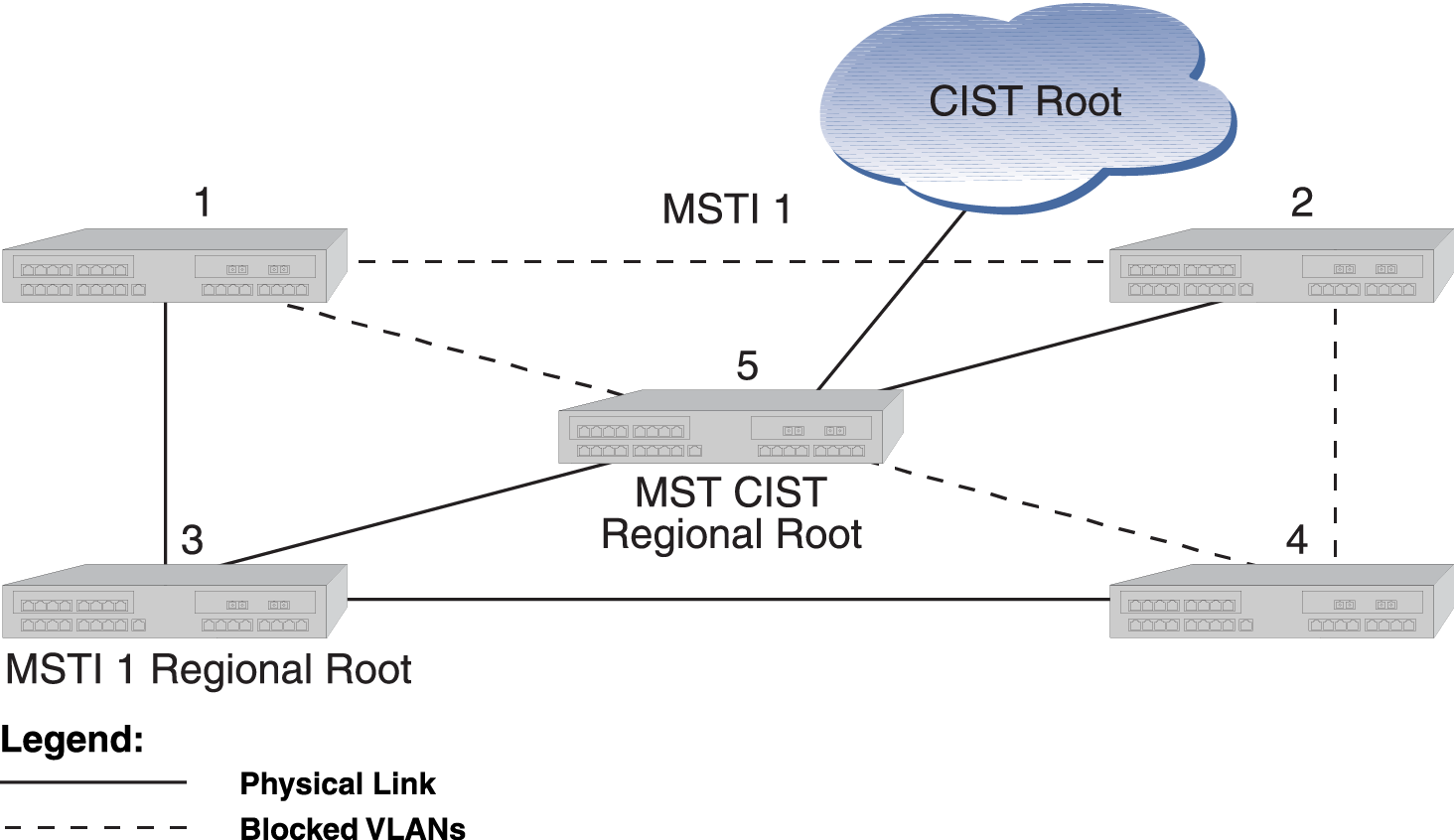
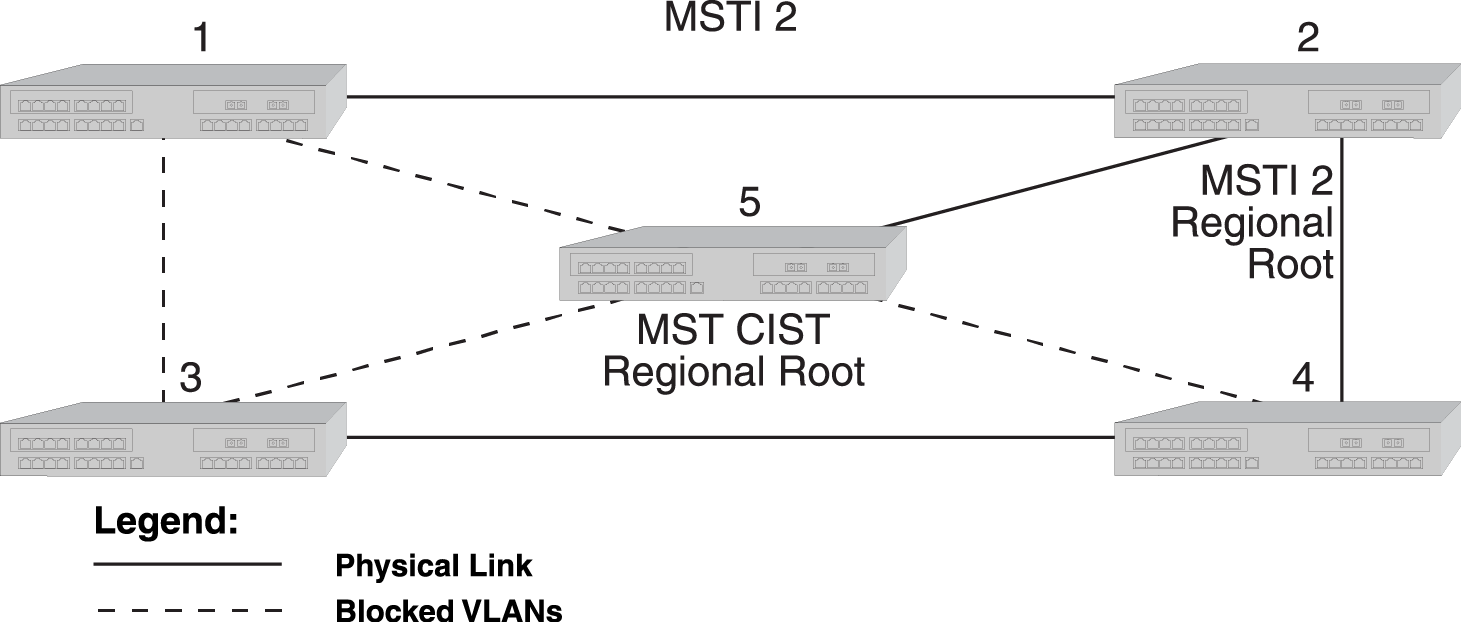
Since an MSTI is a separate Spanning Tree, each MSTI has its own root inside the MST region. MSTI 1 in a Region and MSTI 2 in the Same Region show two MSTIs in a single region. Switching device 3 is the root for MSTI 1, switching device 2 is the root for MSTI 2, and switching device 5 is the CIST regional root. Traffic for all the VLANs attached to an MSTI follow the MSTI‘s spanned topology.
Various options may be configured on a per-MSTI basis to allow for differing topologies between MSTIs. To reduce network complexity and processing overhead needed to maintain MSTIs, you should only create as many MSTIs as needed.
Example of Multiple Regions and MSTIs shows 3 regions with five MSTIs. MSTI Characteristics for Multiple Regions and MSTIs defines the characteristics of each MSTI. Ports connected to PCs from devices 1, 3, 9, and 11 will be automatically detected as edge ports. Devices 4 and 10 are the CIST regional roots. Each MSTI can be configured to forward and block various VLANs.
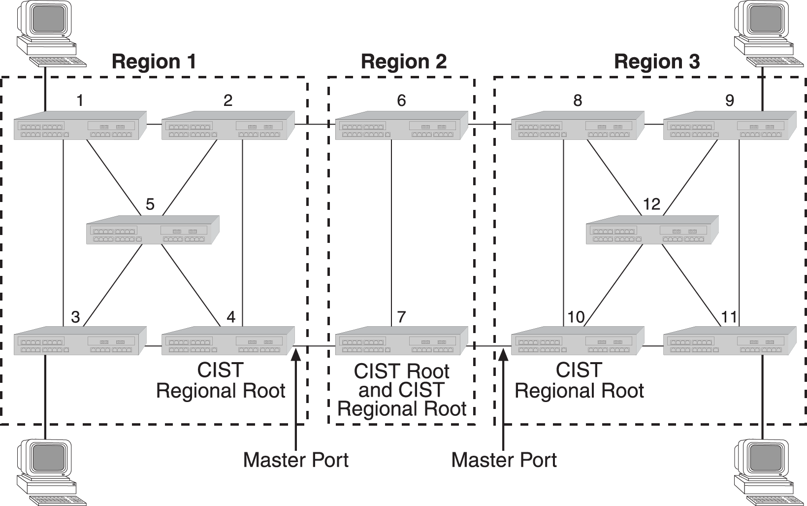
MSTI Characteristics for Multiple Regions and MSTIs
| MSTI / Region | Characteristics |
|---|---|
| MSTI 1 in Region 1 | Root is switching device 4, which is also the CIST regional root |
| MSTI 2 in Region 1 | Root is switching device 5 |
| MSTI 1 in Region 2 | Root is switching device 7, which is also the CIST root |
| MSTI 1 in Region 3 | Root is switching device 11 |
| MSTI 2 in Region 3 | Root is switching device 12 |
| Switching device 10 is the CIST regional root |
 Print
this page
Print
this page Email this topic
 Feedback
 View PDF
 Download EPUB