This example illustrates the use of MSTP for maximum bandwidth utilization. Maximum bandwidth utilization takes place when all bridges participate on all VLANs. Maximum Bandwidth Utilization in a Single STP Network Configuration shows that with a single Spanning Tree configuration, only a single link towards the root forwards on a bridge. The alternate ports are blocking.
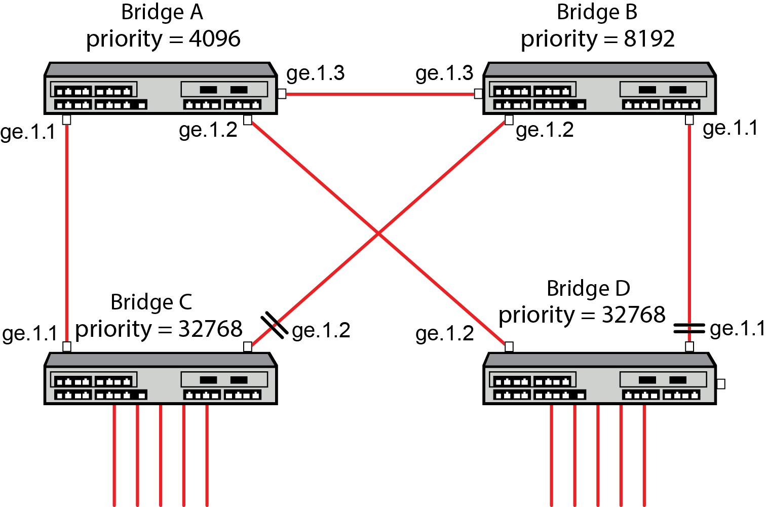
In the figure above, Bridge A is the root of the Spanning Tree because it has the lowest priority. Bridge D port ge.1.2 forwards traffic to Bridge A. Bridge D port ge.1.1 is blocking. Bridge C port ge.1.1 forwards traffic to Bridge A. Bridge C port ge.1.2 is blocking. This single Spanning Tree configuration prevents maximum bandwidth utilization for this network.
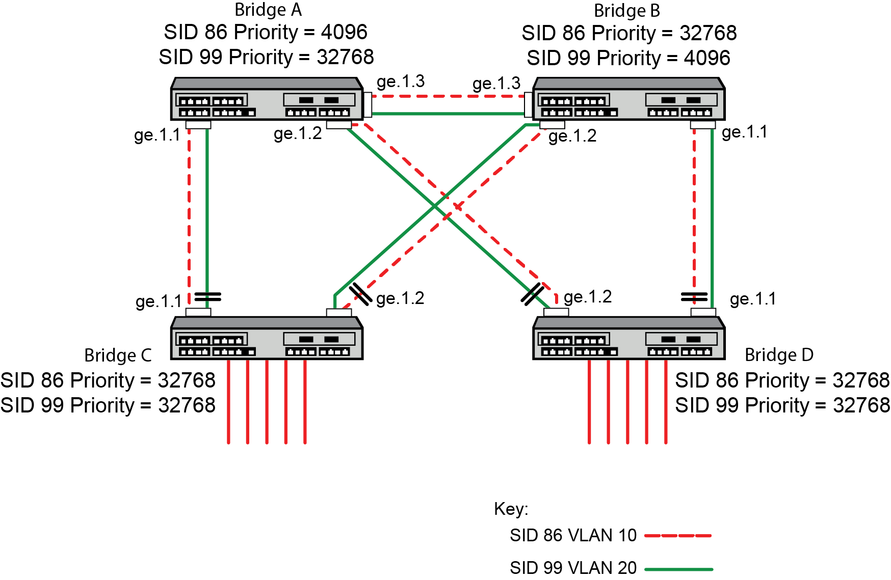
The figure below shows that with an MSTP configuration each link can be forwarding for some VLAN and each VLAN has a path to the root bridge.
To configure the MSTP maximum bandwidth utilization example on all bridges:
set vlan create vlan-id
set spantree mstcfgid cfgname name
set spantree msti sid sid create
set spantree mstmap vlan-id sid sid
Additionally, the root of each SID is chosen to be in a different bridge. This will spread out the traffic. The bridges on the next level down have a link to each of the root bridges.
To configure Bridge A as root for SID 86, set the priority to 4096 for SID 86.
set spantree priority priority sid
To configure Bridge B as the root for SID 99, set the priority to 4096 for SID 99.
 Print
this page
Print
this page Email this topic
 Feedback
 View PDF
 Download EPUB