When creating or modifying a WLAN, the Basic Configuration screen is the first screen that displays as part of the WLAN configuration screen flow. Use this screen to enable a WLAN and to and define its SSID, client behavior, and VLAN assignments.
To define a WLAN's basic configuration:
The list of existing WLANs is displayed.
WLANs can also be removed as they become obsolete by selecting Delete.
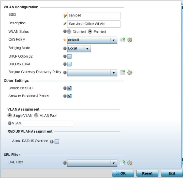
| WLAN | If adding a new WLAN, enter its name in the space provided. Spaces between words or characters are not permitted. The name could be a logical representation of the WLAN support function (engineering, marketing etc.). If editing an existing WLAN, the WLAN's name appears at the top of the screen and cannot be modified. A WLAN name cannot exceed 32 characters. |
| SSID | Enter or modify the Services Set Identification (SSID) associated with the WLAN. The maximum number of characters that can be used for the SSID is 32. |
| Description | Provide a textual description for the WLAN to help differentiate it from others with similar configurations. The description can be up to 64 characters. |
| WLAN Status | Select the Enabled radio button to make this WLAN active and available to clients on all radios where it has been mapped. Select the Disabled radio button to make this WLAN inactive, meaning even if the WLAN is mapped to radios, it is not available for clients to associate and use. |
| QoS Policy | Use the drop-down menu to assign an existing QoS policy to the WLAN or select the Create icon to define a new QoS policy or select the Edit icon to modify the configuration of the selected QoS Policy. QoS helps ensure each WLAN receives a fair share of the overall bandwidth, either equally or per the proportion configured. For information on creating a QoS policy that can be applied to WLAN, see WLAN QoS Policies. |
| Bridging Mode | Use the drop-down menu to specify the WLAN‘s
bridging mode as either Local or Tunnel. Select Local to bridge VLAN traffic locally, or
Tunnel to use a shared tunnel for bridging
the WLAN‘s VLAN traffic. Note: The default setting is Local.
|
| DHCP Option 82 | Select this option to enable DHCP option 82. DHCP Option 82
provides additional information about the physical attachment of a
client. Note: This setting is disabled by default.
|
| DHCPv6 LDRA | Select this option to enable the DHCPv6 relay agent. The DHCPv6
LDRA allows for DHCPv6 messages to be transmitted on existing
networks that do not currently support IPv6 or DHCPv6. Note: This
setting is disabled by default.
|
| Bonjour Gateway Discovery Policy |
Use the drop-down menu to assign an existing Bonjour Gateway Discovery policy to the WLAN. The Bonjour Gateway Discovery Policy configures how Bonjour services can be located on this WLAN. It configures the VLANs on which these services can be found. For more information on Bonjour Gateway Discovery Protocol, see Setting the Bonjour Gateway Configuration. If needed, select the Create icon to define a new Bonjour Gateway Discovery policy or select the Edit icon to modify the configuration of a selected Bonjour Gateway Discovery Protocol. |
| Broadcast SSID |
Select this check box to enable the broadcast of SSIDs within beacons. If a hacker tries to isolate and hack a SSID from a client, the SSID will display since the ESSID is in the beacon. Note: This option is enabled by default.
|
| Answer Broadcast Probes |
Select this check box to associate a client with a blank SSID (regardless of which SSID the wireless controller is currently using). Note: This option is enabled by default.
|
| Single VLAN | Select this radio button to assign just one VLAN to this WLAN. If selecting this option, enter the name of the VLAN within the VLAN parameter field. Utilizing a single VLAN per WLAN is a more typical deployment scenario than using a VLAN pool. |
| VLAN Pool |
Select this option to assign a set of VLANs to this WLAN. Use the table to configure the maximum number of clients that can use the configured per VLAN. Set a value in the range 0 - 8192 clients. |
If RADIUS authentication fails, the VLAN defined is the VLAN assigned to the WLAN.
 Print
this page
Print
this page Email this topic
 Feedback
 View PDF
 Download EPUB