You can add a new port channel configuration or edit an existing configuration.
Select Add to create a new manual session, Edit to modify an existing configuration. To remove a selected port channel configuration select Delete.
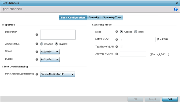
Set the following port channel Properties:
| Description |
Enter a brief description for the port channel (64 characters maximum). The description should reflect the port channel's intended function. |
| Admin Status |
Select the Enabled radio button to define this port channel as active to the profile it supports. Select the Disabled radio button to disable this port channel configuration within the profile. It can be activated at any future time when needed. The default setting is enabled. |
| Speed |
Select the speed at which the port channel can receive and transmit the data. Select either 10 Mbps, 100 Mbps, 1000 Mbps. Select either of these options to establish a 10, 100 or 1000 Mbps data transfer rate for the selected half duplex or full duplex transmission over the port. These options are not available if Automatic is selected. Select Automatic to enable the port channel to automatically exchange information about data transmission speed and duplex capabilities. Auto negotiation is helpful when in an environment where different devices are connected and disconnected on a regular basis. Automatic is the default setting. |
| Duplex |
Select either Half, Full or Automatic as the duplex option. Select Half duplex to send data over the port channel, then immediately receive data from the same direction in which the data was transmitted. Like a Full duplex transmission, a Half duplex transmission can carry data in both directions, just not at the same time. Select Full duplex to transmit data to and from the port channel at the same time. Using Full duplex, the port channel can send data while receiving data as well. Select Automatic to dynamically duplex as port channel performance needs dictate. Automatic is the default setting. |
Use the Port Channel Load Balance drop-down menu to define whether port channel load balancing is conducted using a Source/Destination IP or a Source/Destination MAC. Source/Destination IP is the default setting.
Define the following Switching Mode parameters to apply to the port channel configuration:
| Mode |
Select either the Accessor Trunk radio button to set the VLAN switching mode over the port channel. If Access is selected, the port channel accepts packets only form the native VLANs. Frames are forwarded out the port untagged with no 802.1Q header. All frames received on the port are expected as untagged and are mapped to the native VLAN. If the mode is set to Trunk, the port channel allows packets from a list of VLANs you add to the trunk. A port channel configured as Trunk supports multiple 802.1Q tagged VLANs and one Native VLAN which can be tagged or untagged. Access is the default setting. |
| Native VLAN |
Use the spinner control to define a numerical ID between 1 - 4094. The native VLAN allows an Ethernet device to associate untagged frames to a VLAN when no 802.1Q frame is included in the frame. Additionally, the native VLAN is the VLAN which untagged traffic will be directed over when using trunk mode. The default value is 1. |
| Tag the Native VLAN |
Select the checkbox to tag the native VLAN. WiNG managed devices support the IEEE 802.1Q specification for tagging frames and coordinating VLANs between devices. IEEE 802.1Q adds four bytes to each frame identifying the VLAN ID for upstream devices that the frame belongs. If the upstream Ethernet device does not support IEEE 802.1Q tagging, it does not interpret the tagged frames. When VLAN tagging is required between devices, both devices must support tagging and be configured to accept tagged VLANs. When a frame is tagged, the 12 bit frame VLAN ID is added to the 802.1Q header so upstream Ethernet devices know which VLAN ID the frame belongs to. The device reads the 12 bit VLAN ID and forwards the frame to the appropriate VLAN. When a frame is received with no 802.1Q header, the upstream device classifies the frame using the default or native VLAN assigned to the Trunk port. The native VLAN allows an Ethernet device to associate untagged frames to a VLAN when no 802.1Q frame is included in the frame. This setting is disabled by default. |
| Allowed VLANs |
Selecting Trunk as the mode enables the Allowed VLANs parameter. Add VLANs that exclusively send packets over the port channel. |
Select OK to save the changes made to the port channel Basic Configuration. Select Reset to revert to the last saved configuration.
 Print
this page
Print
this page Email this topic
 Feedback
 View PDF
 Download EPUB