An access point's radio can be configured to form a bridge between its wireless/wired clients and an infrastructure WLAN. The bridge radio authenticates and associates with an infrastructure WLAN access point. After successful association, the access point switches frames between its bridge radio and wired/wireless client(s) connected either to its GE port(s) or to the other radio, thereby providing the clients access to the infrastructure WLAN resources.

Note
WiNG 7.1.X release does not support Client Bridge configuration on AP5XX model access points. This feature will be supported in future releases.
To configure a radio's client bridge settings:
The selected radio's client bridge configuration screen displays.
|
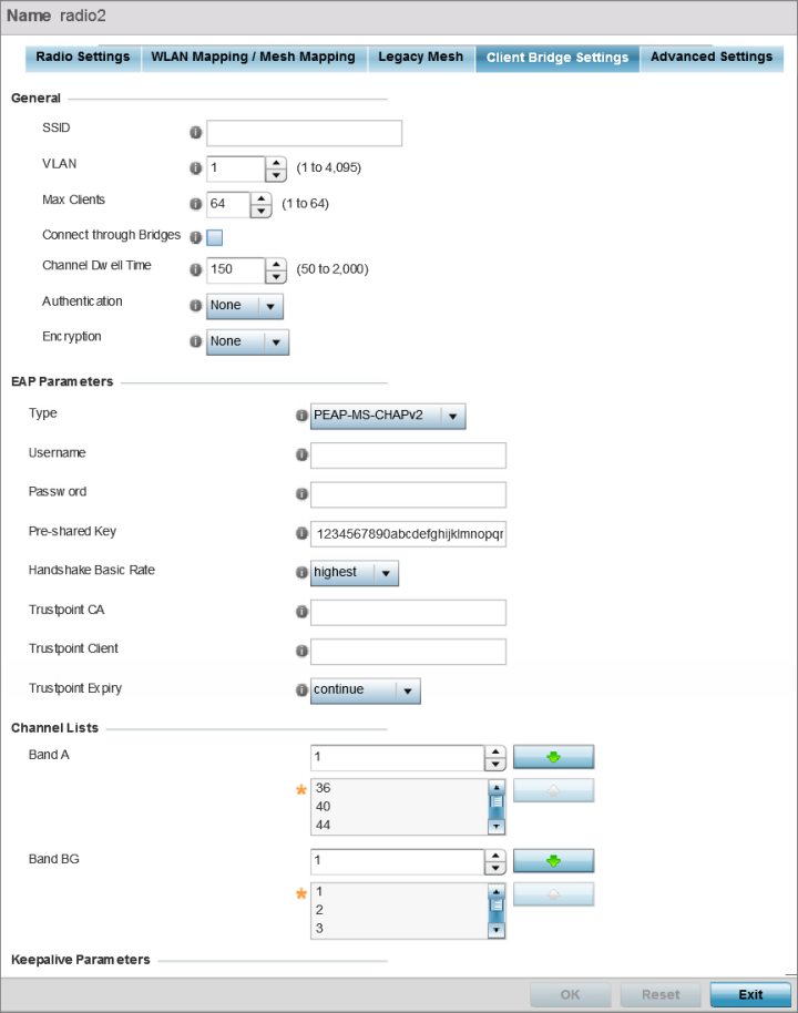
SSID |
Set the infrastructure WLAN‘s SSID, with which the client-bridge access point associates. |
|
VLAN |
Set the VLAN to which the bridged clients‘ sessions are mapped after successful association with the infrastructure WLAN. Once mapped, the client bridge communicates with permitted hosts over the infrastructure WLAN. Specify the VLAN from 1 to 4095. |
|
Max Clients |
Set the maximum number of client-bridge access points that can associate with the infrastructure WLAN. Specify a value from 1 to 64. The default value is 64. |
|
Connect through Bridges |
Select this option to enable the client-bridge access point radio to associate with the infrastructure WLAN through another client-bridge radio thereby forming a chain. This is referred to as daisy chaining of client-bridge radios. This option is disabled by default. |
|
Channel Dwell Time |
Set the channel-dwell time from 50 to 2000 milliseconds. This is the time the client-bridge radio dwells on each channel (configured in the list of channels) when scanning for an infrastructure WLAN. The default is 150 milliseconds. |
|
Authentication |
Set the mode of authentication with the infrastructure WLAN. The authentication mode specified here should be the same as that configured on the infrastructure WLAN. The options are None and EAP. If you select EAP, specify the EAP authentication parameters. The default setting is None. For information on WLAN authentication, see Configuring WLAN Security. |
|
Encryption |
Set the packet encryption mode. The encryption mode specified here should be the same as that configured on the infrastructure WLAN. The options are None, CCMP, and TKIP. The default setting is None. For information on WLAN encryption, see Configuring WLAN Security. |
|
Type |
Select the EAP authentication method used by the supplicant. The options are TLS and PEAP-MS-CHAPv2. The default EAP type is PEAP-MS-CHAPv2. |
|
Username |
Set the 32-character maximum user name for an EAP authentication credential exchange. |
|
Password |
Set the 32-character maximum password for the specified EAP user name. |
|
Pre-shared Key |
Set the PSK (pre-shared key) used with EAP. Note that the authenticating algorithm and PSK should be the same as on the infrastructure WLAN. |
|
Handshake Basic Rate |
Set the basic rate of exchange of handshake packets between the client-bridge and infrastructure WLAN Access Points. The options are highest and normal. The default value is highest. |
|
Trustpoint CA |
Set the Trustpoint CA name (this is the trustpoint installed on the RADIUS server host). This parameter is applicable to both EAP-TLS and PEAP-MS-CHAPv2 authentication modes. In case of both EAP-TLS and PEAP-MS-CHAPv2 authentication, provide the RADIUS server TP name to enable RADIUS server certificate validation at the client end. This parameter is not mandatory for enabling TP-based authentication of CB (Client-Bridge) AP. |
|
Trustpoint Client |
Set the Trustpoint Client name (this is the TP installed on the CB AP). This parameter is applicable only for EAP-TLS authentication mode. When configured, this client certificate is sent across a TLS tunnel and matched for authentication at the RADIUS server host. This configuration is mandatory for enabling TP-based authentication of CB AP. |
|
Trustpoint Expiry |
Use the drop-down menu to specify whether the wireless client-bridge is to be continued or discontinued in case of certificate expiry. In EAP-TLS authentication, a CA-signed certificate is used to authenticate the CB AP and RADIUS server host to establish the wireless CB. Use this option to specify whether the wireless CB is to be continued or terminated on expiration of this certificate. continue – Enables continuation of the CB even after the certificate (CA/client) has expired. When selected, this option enables automatic CA certificate deployment as and when new CA certificates are available. This is the default setting. discontinue – Terminates the CB once the certificate (CA/client) has expired. Note:
Configure this parameter only if the CB AP and the RADIUS server host are using a crypto CMP policy for automatic certificate renewal. For more information, see Crypto CMP Policy. |
|
Band A |
Define a list of channels for scanning across all the channels in the 5.0 GHz radio band. |
|
Band BG |
Define a list of channels for scanning across all the channels in the 2.4 GHz radio band. |
|
Keepalive Type |
Set the keepalive frame type exchanged between the client-bridge and infrastructure access points. This is the type of packets exchanged between the client-bridge and infrastructure access points, at specified intervals, to keep the client-bridge link up and active. The options are null-data and WNMP packets. The default value is null-data. |
|
Keepalive Interval |
Set the keepalive interval from 0 to 86,400 seconds. This is the interval between two successive keepalive frames exchanged between the client-bridge and infrastructure Access Points. The default value is 300 seconds. |
|
Inactivity Timeout |
Set the inactivity timeout for each bridge MAC address from 0 to 864,000 seconds. This is the time for which the client-bridge access point waits before deleting a wired/wireless client‘s MAC address from which a frame has not been received for more than the time specified here. For example, if the inactivity time is set at 120 seconds, and if no frames are received from a client (MAC address) for 120 seconds, it is deleted. The default value is 600 seconds. |
|
Shutdown Other Radio when Link Goes Down |
Select this option to enable shutting down of the non-client bridge radio (this is the radio to which wireless clients associate) when the link between the client-bridge and infrastructure access points is lost. When enabled, wireless clients associated with the non-client bridge radio are pushed to search for and associate with other access points having backhaul connectivity. This option is disabled by default. If you enable this option, specify the time for which the non-client bridge radio is shut down. Use the spinner to specify a time from 1 - 1,800 seconds. |
|
Refresh VLAN Interface when Link Comes Up |
Select this option to enable the SVI to refresh on re-establishing client bridge link to the infrastructure access point. If you are using a DHCP assigned IP address, this option also causes a DHCP renew. This option is enabled by default. |
|
Seconds for Missed Beacons |
Set this interval from 0 to 60 seconds. This is the time for which the client-bridge access point waits, after missing a beacon from the associated infrastructure WLAN access point, before roaming to another infrastructure access point. For example, if Seconds for Missed Beacon is set to 30 seconds, and if more than 30 seconds have passed since the last beacon received from the infrastructure access point, the client-bridge access point resumes scanning for another infrastructure access point. The default value s 20 seconds. |
|
Minimum Signal Strength |
Set the minimum signal-strength threshold for signals received from the infrastructure access point. Specify a value from -128 to -40 dBm. If the RSSI value of signals received from the infrastructure access point falls below the value specified here, the client-bridge access point resumes scanning for another infrastructure access point. The default is -75 dBm. |
Click Reset to revert to the last saved configuration.
 Print
this page
Print
this page Email this topic
 Feedback
 View PDF
 Download EPUB