Using the Initial Setup Wizard
This chapter describes how to use
the
Initial Setup
Wizard to bring up an
access point (AP), with minimal
configurations, to access the wireless network. When bringing up an AP for the first
time, use the wizard to define the AP‘s basic, required settings, such as operational
mode, deployment location, basic security, network and WLAN settings. Once the AP is up
and running, use the AP's GUI to configure the remaining, advanced, user-interface
functionalities.
To bring up an AP for the first time, follow the steps
below:
-
Install and power up the AP.
-
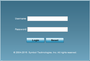
Point the Web browser to the AP's IP
address.
The AP's Web UI login screen
displays.
-
Enter the default user name
admin
in the User
name field.
-
Enter the default password
admin123 in the Password
field.

Note
When logging in for the
first time, you will be prompted to change the password. Set a new password
and use it for subsequent logins.
The
AP's management interface UI displays, and the
Initial
Setup Wizard landing page pops up.
Note
The
Initial Setup Wizard displays the same
pages and content for all the WiNG AP model types – the
only difference being the number of radios supported on
the AP.
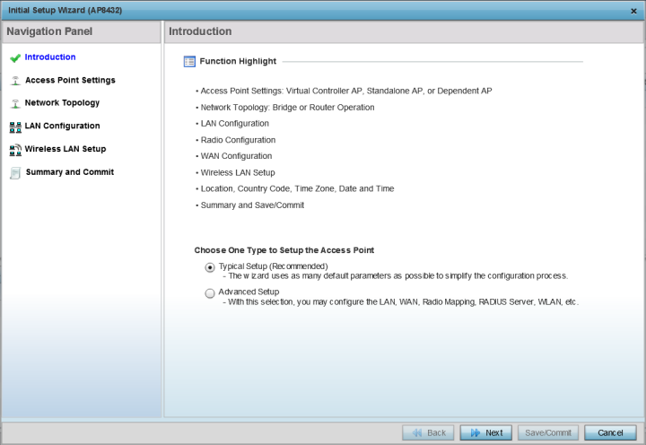
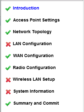
The landing page has the following
elements:
| Introduction: |
Lists the tasks you can perform using this
wizard. |
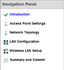
| Navigation Panel: |
Provides links to configuration pages where you
can perform the tasks listed in the Introduction pane. |
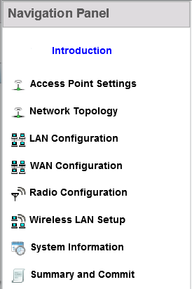
| Choose One Type to Setup the Access Point |
Provides two AP setup wizards. The options are:
Typical Setup and Advanced Setup. The links
available on the Navigation Panel vary depending
on the option you select. |
Selecting the Access Point Setup
Wizard Type.
-
Select one of the following AP setup
wizards:
A green check-mark to the left of a task,
on the
Navigation
Panel, indicates that the minimum required configurations for
that task have been set correctly. It is mandatory to have each task green
check-marked to successfully complete the initial setup.
A
red X against a task indicates that at least one mandatory parameter is
pending configuration.
-
Select the Summary and Commit link, on
the Navigation Panel, to view and commit your
changes.
-
Select Next to proceed to the next
page.
Select
Back to
revert to the previous page without saving your updates.
Select Cancel to close the
wizard without committing your changes.
Select Save/Commit to save
changes made to a page. We recommend that you save your updates before
moving to the next page.
Tasks Common to both Wizard
Types.
The following steps describe tasks that are common to both
wizards.
-
Click Next.
The
Access Point
Settings page displays. Use this page to specify the AP's mode of
functioning.
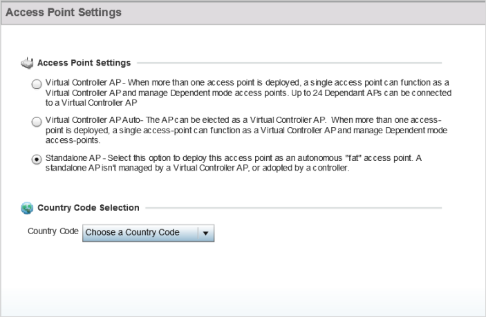
Configuring the Access Point Settings.
-
Set the AP's mode of functioning as one of the
following:
- Virtual Controller AP - Select to
configure the AP to function as a virtual controller (VC). In a multiple-AP
network, you can configure one of the APs as the VC. For
information on the adoption capabilities of the
different WiNG AP model types, see GUID-0691D163-E3EF-41E0-8C1F-21A1323B40F5#GUID-0691D163-E3EF-41E0-8C1F-21A1323B40F5.
- Virtual Controller AP
Auto - Select to enable dynamic virtual controller
(DVC) mode on the AP. When enabled, the AP on being elected as the RF Domain
manager takes on the role of the VC. If you have deployed multiple APs in an
RF Domain, you can enable DVC on more than one AP. However, only the current
RF Domain manager AP has a running instance of the DVC.
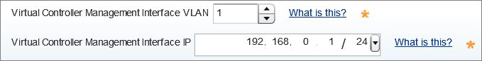
If enabling DVC,
configure the AP's management interface settings:
- Use the Virtual
Controller Management VLAN spinner control to set
the management interface's virtual local area network (VLAN).
This VLAN is exclusively used by the VC to broadcast MiNT packets,
and to adopt APs. The default setting is VLAN 1.
- Enter the management
interface IP address and subnet in the Virtual
Controller Management Interface IP field.
Because
of the random nature of DVC, specifying an explicit management
interface IP address makes it easier to manage VCs. In case of
failover, this IP address is installed as the secondary IP
address on the new VC.
Configuring a management interface
IP address is mandatory. However, VLAN configuration is
optional. If you configure the IP address without specifying the
VLAN, the system sets the specified IP address as secondary IP
on VLAN 1.
- Standalone AP
- Select to deploy the AP as an independent AP, not
managed by a VC, or adopted by a wireless controller/service platform.
.
Note
If designating the AP as
a Standalone AP, exclusively use the AP‘s UI, and not the CLI, to
configure the AP's settings. The CLI allows you to define more than one
profile, whereas the UI does not. Consequently, you might encounter
problems if using both interfaces to manage profiles.
- Adopted to
Controller - Select to deploy the AP as a
controller-managed, dependent AP.
Note
The
Adopted to
Controller option is available only on the
Advanced
Setup wizard.
Note
A controller-adopted AP
obtains its configuration from a profile stored on its managing
controller. Manual changes made on the AP are overwritten by the
controller upon reboot.
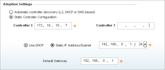
If enabling controller adoption,
configure the following Adoption
Settings:
- Select Automatic
controller discovery (L2, DHCP or DNS based) to
enable dynamic discovery and adoption of the AP by any controller
within the same subnet. The AP is Layer 2 (L2) adopted to the
controller.
- Select Static Controller
Configuration to manually configure the controller
to which the AP should adopt. This is applicable only in case of
Layer 3 (L3) adoption.
If enabling L3 adoption:
-
Use the Country Code
Selection spinner control to set the AP's country of deployment.
Ensure that the country code is
set correctly because parameters – for example, the available channels of
operation and regulatory compliance rules – are country specific.
This option
is available only on the Typical Setup
wizard.
-
Select Next.
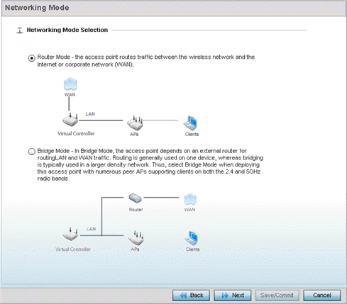
The
Networking Mode page displays. Use this page to define
the AP's network-traffic handling mode.
Configuring the AP's Network Topology
Settings.
-
Set the AP's Networking Mode Selection
as:
- Router Mode -
Select to enable the AP to function as a router. When enabled, the AP routes
traffic between the local area network (LAN) and the Internet or
external wide area network (WAN). We recommend using this option in
single-AP supported deployments.
- Bridge Mode - Select to
enable the AP function as a bridge between the LAN and the Internet or WAN.
When enabled, the AP uses an external router to bridge traffic. We recommend
using this option in multiple-AP deployments, with APs supporting clients on
both the 2.4 GHz and 5.0 GHz radio bands.
Note
The
Bridge Mode does not require WAN configurations on the
AP. Therefore, if you select this option, the WAN configuration option
is disabled.
-
Select Next.
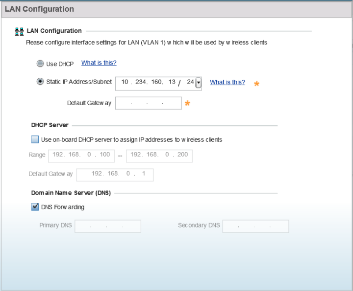
The
LAN Configuration screen
displays. Use this screen to configure the AP's LAN address, DHCP server, and
DNS server.
Configuring the AP's LAN
Settings.
-
Select one of the following options to configure
the IP address of the AP's LAN interface:
- Use DHCP - Select to
enable dynamic IP address assignment. When selected, the local DHCP server
resource, running on VLAN 1 (the default VLAN), assigns the IP address.
Note
If you select this option, the
AP's VLAN 1 (the default VLAN interface of the AP) is dynamically
assigned an IP address by the DHCP server running on VLAN 1. Therefore,
if you select this option, ensure that a DHCP server is up and running
on VLAN 1 and is reachable from the AP.
- Static IP Address/Subnet
- Select to manually configure the AP's IP address and subnet.
- Enter the AP's LAN interface IP address and
subnet in the Static
IP Address/Subnet field.
- Enter the default gateway's IP address in the
Default
Gateway field.
Note
The AP
routes inter-VLAN traffic through the default
gateway.
Note
If you configure a static
IP and subnet for the AP, also enable it to function as an on-board DHCP.
Therefore, if you select this option, configure the DHCP server and DNS
server settings. For DHCP server configurations, move to step
15. For
DNS server configurations, move to step
16.
-
Set the following DHCP Server settings:
-
Select the Use on-board DHCP server to
assign IP addresses to wireless clients option to enable
the AP to function as the on-board DHCP server resource.
When this option is enabled, the
AP provides its IP address to requesting wireless clients on the LAN
interface.
-
Enter the starting and ending IP addresses
in the Range
fields.
The AP assigns IP addresses to
authenticated wireless clients from the specified range.
Avoid assigning IP addresses from
x.x.x.1 - x.x.x.10 and x.x.x.255, as they are often reserved for
standard network services.
-
Enter the IP address of the default
gateway, in the Default
Gateway field.
-
Select one of the following options to configure
the Domain Name Server
:
Configuring the AP's WAN settings.
-
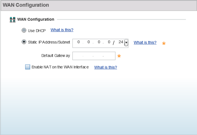
Select Next.
The
WAN Configuration
page displays. Use this page to define network address settings for the AP's WAN
interface. The WAN interface connects the AP to the wired local area network or
backhaul.
Note
The WAN
Configuration option is enabled only if you set the AP in
Router Mode
on the
Networking
Mode page (see step
11 ).
-
Select one of the following options to configure the AP's WAN interface's IP
address:
- Use DHCP - Select to
enable dynamic IP address assignment. When selected, an external DHCP server
resource, located on the WAN side of the network, assigns an IP address to
the AP‘s WAN interface.
- Static IP Address/Subnet
- Select to manually configure IP address and subnet for the AP's WAN
interface.
-
Select Next.
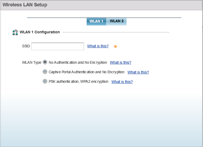
The
Wireless LAN Setup page displays. Use this
page to configure the AP's
Wireless
Local Area Network (WLAN) settings.
A WLAN is a means of flexibly extending the
functionality of a wired
LAN. A WLAN links two or more computers or
devices using spread-spectrum or OFDM modulation based
technology. WLANs do not require lining up devices for
line-of-sight transmission, and are thus desirable for
wireless networking. Roaming users can be handed off
from one AP to another, as with a cellular phone system.
WLANs can therefore be configured around the needs of
specific user groups, even when they are not in physical
proximity.
Configuring the WLAN Settings.
Note
You can configure up to two (2) WLANs
for the AP.
-
Set the following WLAN parameters:
-
Enter the WLAN's
SSID.
-
Select the WLAN Type.
The WLAN Type defines the encryption and authentication modes used
with the WLAN.
- No Authentication and No Encryption
– Select to configure a network without any authentication or
encryption.
Note
When selected, any device can access
the network. Data transmitted through the network is in plain
text.
- Captive Portal
Authentication and No Encryption – Select to configure a
network using Captive Portal (Web page) based authentication.
Note
When selected, the
network serves a Web page (internally or externally hosted) to wireless
clients requesting network access. The clients enter their login
credentials on this Web page. These credentials are authenticated by a
RADIUS server. On successful authentication clients are granted access.
Once on the network, the data transmitted through the network is in
plain text.
Note
If selecting this option, move to step
21 to configure the RADIUS server details.
- PSK authentication, WPA2
encryption – Select to configure a network that uses PSK
authentication and WPA2 encryption.
Note
When selected, wireless
clients are granted network access only if the
pre-shared key
(PSK) configured on the AP matches the PSK configured on the
client.
Note
If
selecting this option, move to step
22 to configure the PSK.
Configuring RADIUS server for the
Captive Portal Authentication and No Encryption network.
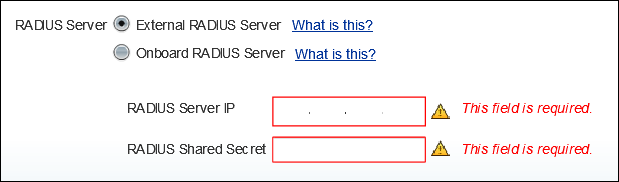
-
Specify the RADIUS Server type
as one of the following:
- External RADIUS
Server - Select to use an externally hosted RADIUS server
for user authentication. This is the default setting.
- Enter the external
RADIUS server resource IP address in the RADIUS Server IP
address field.
- Enter the shared
secret needed to access the RADIUS server, in the RADIUS Shared
Secret field.
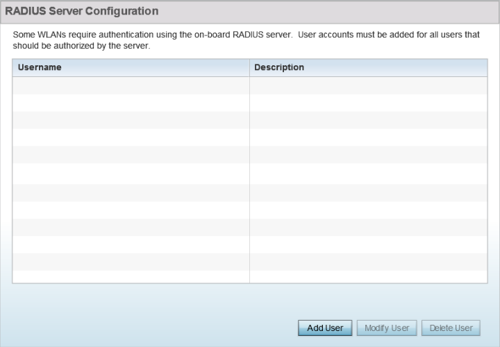
- Onboard RADIUS
Server – Select to configure the AP as the RADIUS server
that performs user authentication. A RADIUS Server
Configuration window is displayed, where you add users to the
RADIUS server database.
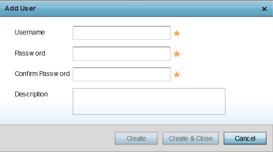
- Click Add
User to add a new user. The Add
User dialog displays.
| User name |
Enter
the client's user name. |
| Password |
Enter
the password associated with the specified user
name. |
| Confirm Password |
Re-enter the password. |
| Description |
Enter
a short description for the user. |
- Click Create to add the new user and continue adding
other users.
- Click Create &
Close to add the new user and close the
dialog.
- To modify an
existing user in the RADIUS server database, select the user
from those listed and click Modify
User. In the Modify
User dialog, make the required changes and click
Modify User.
Note
You cannot
modify the Username. However, Password and Description can
be modified.
- To delete an
existing user in the RADIUS server database, select the user
from those listed and click Delete
User. A confirmation dialog displays. Click
Yes to confirm deletion.
Configuring PSK for the PSK
authentication, WPA2 encryption network.
-
To specify the PSK needed for client
authentication:
-
Use the drop-down menu to specify the PSK
type as ASCII or HEX.
-
Enter the PSK in the
WPA
Key field.
Provide a 64-character HEX key or an 8-63 character ASCII key, based
on the PSK type you have selected.
Advanced Setup-specific Tasks.
The following steps describe the tasks specific to the
Advanced Setup
wizard.
-
Click Next.
The
Radio Configuration page displays. Use this
page to set the radio's mode of operation. The radio can be
set to transmit data to and from wireless clients, or it can
be configured to function as a dedicated sensor.
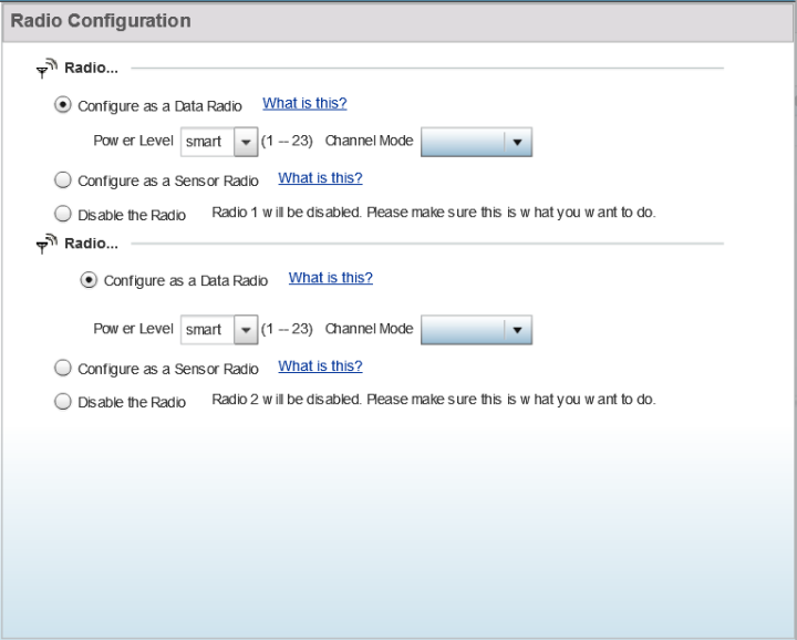
Note
The
number of configurable radios displayed depends on the
AP's model type.
The following image shows an
AP with two radios:
Configuring the AP's Radio Interface.
-
Set the following parameters for each radio:
-
Configure as a Data Radio
- Select to dedicate the radio to WLAN client support in the
2.4 GHz or 5.0 GHz radio bands.
-
Power Level - Use the
spinner control to select a 1 - 23 dBm minimum power level to assign to
this radio. 1 dBm is the default setting.
-
Channel Mode - Set
the channel selection mode to one of the following:
| Random |
Select to use
with 802.11n radios. In the European Union, to comply with
Dynamic Frequency Selection (DFS) requirements, the
802.11n radio uses a randomly selected channel each time the
AP is powered on. |
| Best |
Select to enable the AP to scan non-overlapping channels and
listen for beacons from other APs. After the channels are
scanned, the AP selects the channel with the fewest APs. In
case of multiple APs on the same channel, it selects the
channel with the lowest average power level. Selecting
Best enables the Constantly
Monitor option. Select this option to enable
the AP to continuously scan the network for excessive noise
and sources of interference. |
| Static |
Select to assign the AP a permanent channel and scan for
noise and interference only when initialized. |
-
Configure as a Sensor
Radio - Select to dedicate the radio to sensor support
exclusively. A sensor radio scans all channels within the 2.4 and 5.0
GHz bands to identify potential threats. If you are dedicating the radio
to sensor support, also configure a primary and secondary ADSP server,
that receives and analyses inputs from the sensor radio.
-
Disable the Radio -
Select to disable the radio. When disabled, the radio goes offline.
Verify this course of action with your network administrator before
rendering the radio offline.
-
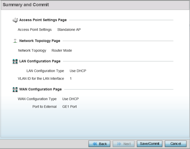
Click Next.
The
Summary and
Commit page displays.
Note
This page is
available on both the
Typical
Setup and
Advanced Setup wizards.
Use this page to review and validate the AP's
configuration.
- If the AP's
configuration warrants additional changes, click Back,
navigate to the desired page, and make the changes.
- After you have validated the configurations,
click Save/Commit to apply the changes.
 Print
this page
Print
this page Email this topic
 Feedback
 View PDF
 Download EPUB