WLANs use Firewalls like Access Control Lists (ACLs) to filter/mark packets based on the WLAN from which they arrive, as opposed to filtering packets on Layer 2 ports. An ACL contains an ordered list of Access Control Entries (ACEs). Each ACE specifies an action and a set of conditions (rules) a packet must satisfy to match the ACE. The order of conditions in the list is critical since filtering is stopped after the first match.
IP based Firewall rules are specific to source and destination IP addresses and the unique rules and precedence orders assigned. Both IP and non-IP traffic on the same Layer 2 interface can be filtered by applying both an IP ACL and a MAC.Additionally, administrators can filter Layer 2 traffic on a physical Layer 2 interface using MAC addresses. A MAC Firewall rule uses source and destination MAC addresses for matching operations, where the result is a typical allow, deny or mark designation to WLAN packet traffic.
A MAC Firewall rule uses source and destination MAC addresses for matching operations, where the result is a typical allow, deny or mark designation to WLAN packet traffic.Keep in mind that IP and non-IP traffic on the same Layer 2 interface can be filtered by applying both an IP ACL and a MAC ACL to the interface.
To review existing Firewall configurations, create a new Firewall configuration or edit the properties of a WLAN‘s existing Firewall:
If no rules exist, select the Create icon to create a new firewall rule configuration. Select the Edit icon to modify the configuration of a selected Firewall policy configuration.
If you are creating a new rule, provide a name up to 32 characters.

Note
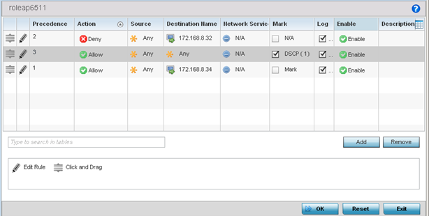
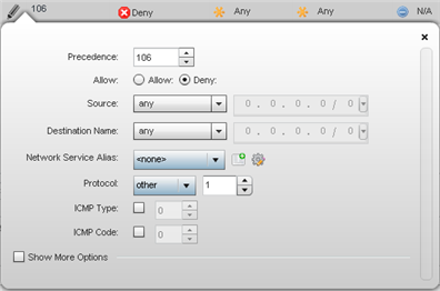
Only those selected IP ACL filter attributes display. Each value can have its current setting adjusted by selecting that IP ACL‘s column to display a pop-up to adjust that one value.| Precedence | Specify or modify a precedence for this IP policy between 1 and 5000. Rules with lower precedence are always applied to packets first. If you modify a precedence to apply a higher integer, it will move down the table to reflect its lower priority. | ||||
| Action | Every IP Firewall rule is made up of matching criteria rules. The action defines what to do with the packet if it matches the specified criteria. The following actions are supported:
|
||||
| DNS Name | Specify the DNS Name which may be a full domain name, a portion of a domain name or a suffix. This name is used for the DNS Match Type criteria. | ||||
| DNS Match Type | Specify the DNS matching criteria that the DNS Name can be matched against. This can be configured as an exact match for a DNS domain name, a suffix for the DNS name or a domain that contains a portion of the DNS name. If traffic matches the configured criteria in the DNS Match Type, that rule will be applied to the ACL. | ||||
| Source | Select the source IP address or network group configuration used as basic matching criteria for this IP ACL rule. Source options include:
|
||||
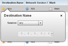
| Destination | Select the destination IP address or network group configuration used as a basis matching criteria for this IP ACL rule. Destination options include:
|
||||
| Protocol | Select the protocol to filter for this ACL. Use the drop down to select from a list of predefined protocol or use the spinner control to set a particular protocol number. | ||||
| Network Service Alias | The service alias is a set of configurations consisting of protocol and port mappings. Both source and destination ports are configurable. Set an alphanumeric service alias (beginning with a $) and include the protocol as relevant. Selecting either tcp or udp displays an additional set of specific TCP/UDP source and destination port options. | ||||
| Source Port | If you are using either
tcp or
udp as the protocol, define whether the source port for incoming IP ACL rule application is
any,
equals, or an administrator defined range. If you are not using
tcp or
udp, this setting displays as N/A. This is the data local origination port designated by the administrator. Selecting
equals invokes a spinner control for setting a single numeric port.
Selecting equals invokes a spinner control for setting a single numeric port. Selecting range displays spinner controls for low and high numeric range settings. A source port cannot be a destination port. |
||||
| Destination Port | If you are using either
tcp or
udp as the protocol, define whether the destination port for outgoing IP ACL rule application is
any,
equals, or an administrator defined range. If you are not using
tcp or
udp, this setting displays as N/A. This is the data destination virtual port designated by the administrator.
Selecting equals invokes a spinner control for setting a single numeric port. Selecting range displays spinner controls for low and high numeric range settings. A source port cannot be a destination port. |
||||
| ICMP Type | Selecting ICMP as the protocol for the IP rule displays an additional set of ICMP specific options for ICMP type and code. The ICMP (Internet Control Message Protocol) uses messages identified by numeric type. ICMP messages are used for packet flow control or generated in IP error responses. ICMP errors are directed to the source IP address of the originating packet. Assign an ICMP type from 1-10. | ||||
| ICMP Code | Selecting ICMP as the protocol for the IP rule displays an additional set of ICMP specific options for ICMP type and code. Many ICMP types have a corresponding code, helpful for troubleshooting network issues, for example 0 - Net Unreachable, 1 - Host Unreachable, and 2 - Protocol Unreachable. | ||||
| Start VLAN | Select a Start VLAN icon within a table row to set (apply) a start VLAN range for this IP ACL filter. The Start VLAN represents the virtual LAN beginning numeric identifier arriving packets must adhere to in order to have the IP ACL rules apply. | ||||
| End VLAN | Select an End VLAN icon within a table row to set (apply) an end VLAN range for this IP ACL filter. The End VLAN represents the virtual LAN end numeric identifier arriving packets must adhere to in order to have the IP ACL rules apply. | ||||
| Mark | Select this option to mark certain fields inside a packet before allowing them. Mark applies only for Allow rules. Mark sets the rule‘s 802.1p or dscp level (from 0 - 7) | ||||
| Log | Select this option to create a log entry that a firewall rule has allowed a packet to be either denied or allowed. | ||||
| Enabled | Select this option to enable or disable this particular IP Firewall rule in this rule set. | ||||
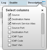
| Description | Lists the administrator assigned description applied to the IP ACL rule. Select a description within the table to modify its character string as filtering changes warrant. Select the icon within the Description table header to launch a Select Columns screen used to add or remove IP ACL criteria from the table. |
If creating a new rule, provide a name up to 32 characters.
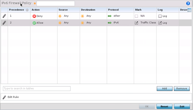
IPv6 Firewall rule configurations can either be modified as a collective group of variables or selected and updated individually as their filtering attributes require a more refined update.
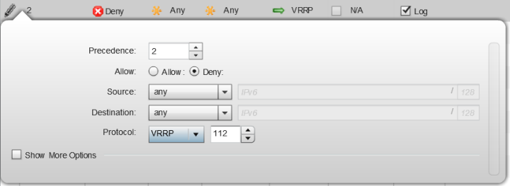
| Precedence | Specify or modify a precedence for this IPv6 policy between 1-1500. Rules with lower precedence are always applied to packets first. If modifying a precedence to apply a higher integer, it will move down the table to reflect its lower priority.
The Precedence column sets the priority of a IPv6 Firewall rule within its rule set. |
||||
| Action | Every IPv6 Firewall rule is made up of matching criteria rules. The action defines what to do with the packet if it matches the specified criteria. The following actions are supported:
|
||||
| Source | Select the source IPv6 address or network group configuration used as a basis matching criteria for this IPv6 ACL rule. Source options include:
|
||||
| Destination | Select the destination IPv6 address or network group configuration used as a basis matching criteria for this IPv6 ACL rule. Destination options include:
|
||||
| Protocol | Select the protocol to filter for this IPv6 ACL. Use the drop down to select from a list of predefined protocol or use the spinner control to set a particular protocol number. | ||||
| Source Port | If you are using either
tcp or
udp as the protocol, define whether the source port for incoming IPv6 ACL rule application is
any,
equals, or an administrator defined range. If you are not using
tcp or
udp, this setting displays as N/A. This is the data local origination port designated by the administrator. Selecting
equals invokes a spinner control for setting a single numeric port.
Selecting equals invokes a spinner control for setting a single numeric port. Selecting range displays spinner controls for low and high numeric range settings. A source port cannot be a destination port. |
||||
| Destination Port | If you are using either
tcp or
udp as the protocol, define whether the destination port for outgoing IPv6 ACL rule application is
any,
equals, or an administrator defined range. If you are not using
tcp or
udp, this setting displays as N/A. This is the data destination virtual port designated by the administrator.
Selecting equals invokes a spinner control for setting a single numeric port. Selecting range displays spinner controls for low and high numeric range settings. A source port cannot be a destination port. |
||||
| ICMP Type | Selecting ICMP as the protocol for the IPv6 rule displays an additional set of ICMP specific options for ICMP type and code. The Internet Control Message Protocol (ICMP) uses messages identified by numeric type. ICMP messages are used for packet flow control or generated in IP error responses. ICMP errors are directed to the source IP address of the originating packet. Assign an ICMP type from 1-10. | ||||
| ICMP Code | Selecting ICMP as the protocol for the IPv6 rule displays an additional set of ICMP specific options for ICMP type and code. Many ICMP types have a corresponding code, helpful for troubleshooting network issues, for example 0 - Net Unreachable, 1 - Host Unreachable, and 2 - Protocol Unreachable. | ||||
| Mark | Select this option to mark certain fields inside a packet before allowing them. Mark applies only for Allow rules. Mark sets the rule‘s 802.1p or dscp level (from 0 - 7) | ||||
| Log | Select this option to create a log entry that a firewall rule has allowed a packet to be either denied or allowed. | ||||
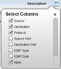
| Description | Lists the administrator assigned description applied to the IPv6 ACL rule. Select a description within the table to modify its character string as filtering changes warrant. Select the icon within the Description table header to launch a Select Columns screen used to add or remove IPv6 ACL criteria from the table. |
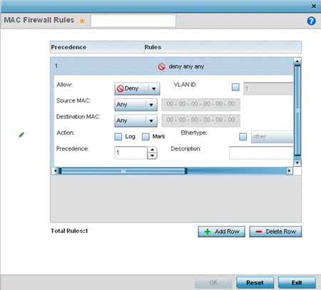
| Allow | Every IP Firewall rule is made up of matching criteria rules. The action defines what to do with the packet if it matches the specified criteria. The following actions are supported:
|
||||||
| Source and Destination MAC | Enter both Source and Destination MAC addresses. The access point uses the source IP address, destination MAC address as basic matching criteria. Provide a subnet mask if using a mask. | ||||||
| Actions | The following actions are supported:
|
||||||
| Traffic Class | Sets an ACL traffic classification value for the packets identified by this inbound MAC filter. Traffic classifications are used for QoS purposes. Use the spinner to define a traffic class from 1- 10. | ||||||
| Precedence | Use the spinner control to specify a precedence for this MAC Firewall rule between 1-1500. Access policies with lower precedence are always applied first to packets. | ||||||
| VLAN ID | Enter a VLAN ID representative of the shared SSID each user employs to interoperate within the network (once authenticated by the access point‘s local RADIUS server). Set the VLAN form 1 - 4094. | ||||||
| Match 802.1P | Configures IP DSCP to 802.1p priority mapping for untagged frames. Use the spinner control to define a setting from 0 - 7. | ||||||
| Ethertype | Use the drop-down menu to specify an Ethertype of either ipv6, arp, wisp or monitor 8021q. An EtherType is a two-octet field within an Ethernet frame. It is used to indicate which protocol is encapsulated in the payload of an Ethernet frame. When other is selected, the ethertype value can be configured manually. | ||||||
| Description | Provide an ACL setting description (up to 64 characters) for the rule to help differentiate it from others with similar configurations. |
| Precedence | Enter a numerical value indicating the precedence of rule execution. | ||||
| Starting MAC Address | Enter a MAC address to define the start of range. This field is mandatory. | ||||
| Ending MAC Address | Enter a MAC address to define the end of range. | ||||
| Allow/Deny | Every Association ACL rule consists of matching criteria rules. The action defines what to do with the device if it matches the specified criteria. The following actions are supported:
|
| Application Policy | Use the drop-down menu to assign an application policy to the WLAN‘s firewall
configuration. When an application is recognized and
classified by the WiNG application recognition engine,
administrator defined actions can be applied to that
application. An application policy defines the rules or
actions executed on recognized HTTP, SSL and .voice/video
applications. For more information, refer to Application. Note: The WiNG
7.1.X release does not support third-party DPI engine on
the AP5XX model access points. WiNG 7.1.2 supports
EAA (Extreme Application Analytics) (Purview™) DPI
engine on the WiNG 7.1.X APs. For more information,
refer the WiNG 7.1.2 CLI Reference guide, available at
https://extremenetworks.com/documentation.
|
| Voice/Video Metadata | Select this option to enable the extraction of voice and video
metadata flows. When enabled,
administrators can track voice and video
calls by extracting parameters (packets
transferred and lost, jitter, audio
codec and application name). Most
Enterprise VoIP applications like
Facetime, Skype for Business, and VoIP
terminals can be monitored for call
quality and visualized on the Extreme
NSight UI in manner similar to HTTP and
SSL. Call quality and metrics can be
determined only from calls that are
established as unencrypted. This setting
is disabled by default. Note:
Starting with WiNG 5.9.3, NSight is a separate target. For information on Extreme NSight™, refer to the Extreme NSight User Guide available at https://extremenetworks.com/documentation. |
| HTTP Metadata | Select this option to enable the extraction of HTTP flows. When
enabled, administrators can track HTTP
Websites accessed by both internal and
guest clients and visualize HTTP data
usage, hits, active time and total
clients on the Extreme NSight UI. This
setting is disabled by default. Note:
Starting with WiNG 5.9.3, NSight is a separate target. For information on Extreme NSight™, refer to the Extreme NSight User Guide available at https://extremenetworks.com/documentation. |
| SSL Metadata | Select this option to enable the extraction of SSL flows. When
enabled, administrators can track SSL
Websites accessed by both internal and
guest clients and visualize SSL data
usage, hits, active time and total
clients on the Extreme NSight UI. This
setting is disabled by default. Note:
Starting with WiNG 5.9.3, NSight is a separate target. For information on Extreme NSight™, refer to the Extreme NSight User Guide available at https://extremenetworks.com/documentation. |
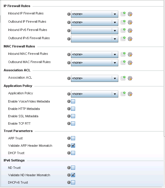
| ARP Trust | Select this option to enable ARP trust on this WLAN. ARP packets received on this WLAN are considered trusted and information from these packets is used to identify rogue devices within the network. This setting is disabled by default. |
| Validate ARP Header Mismatch | Select this option to check for a source MAC mismatch in the ARP header and Ethernet header. This setting is enabled by default. |
| DHCP Trust | Select this option to enable DHCP trust on this WLAN. This setting is disabled by default. |
| ND Trust | Select this option to enable the trust of neighbor discovery requests on an IPv6 supported firewall on this WLAN. This setting is disabled by default. |
| Validate ND Header Mismatch | Select this option to enable a mismatch check for the source MAC within the ND header and Link Layer Option. This setting is enabled by default. |
| DHCPv6 Trust | Select this option to enable the trust all DHCPv6 responses on this WLAN‘s firewall. DHCPv6 is a networking protocol for configuring IPv6 hosts with IP addresses, IP prefixes or other configuration attributes required on an IPv6 network. This setting is disabled by default |
| RA Guard | Select this option to enable router advertisements or ICMPv6 redirects on this WLAN‘s firewall. This setting is disabled by default. |
| Wireless Client Denied Traffic Threshold | When this option is enabled, any associated client, exceeding the thresholds configured for storm traffic, is either deauthenticated or blacklisted depending on the selected action. The threshold range is from 1- 1000000 packets per second. This feature is disabled by default. |
| Action | If you are enabling a wireless client threshold, use the drop-down menu to determine whether clients are deauthenticated when the threshold is exceeded, or blacklisted from connectivity for a user-defined interval. Selecting None applies no consequence to an exceeded threshold. |
| Blacklist Duration | Select this option and define a setting from 0 - 86,400 seconds. Offending clients can reauthenticate, once this blacklist duration has been exceeded. |
 Print
this page
Print
this page Email this topic
 Feedback
 View PDF
 Download EPUB