An access point can have its radio profile configuration overridden after its radios have successfully associated to the network.
This section documents radio interface configuration parameters applicable only to the access point profiles and devices.
The new AP5XX access points are dual radio access point models.
To review an access point's existing radio configurations
The Device Overrides screen displays. This screen lists devices within the managed network.
The selected access point's configuration menu displays.
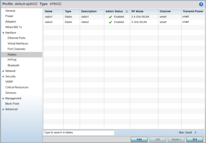
The selected access points radio configurations are displayed.

Note
A blue override icon (to the left of a parameter) defines the parameter as having an override applied. To remove an override go to the Basic Configuration section of the device and click Clear Overrides. This removes all overrides from the device.
|
Name |
Displays whether the reporting radio is radio 1, radio 2 or radio 3. |
|
Type |
Displays whether the radio has been designated as a typical WLAN radio or if the radio has been designated as a sensor. |
|
Description |
A brief description provided by the administrator when the radio's configuration was added or modified. |
|
Admin Status |
A green check mark means the radio is enabled for client or sensor support. A red “X” means the radio is currently disabled. |
|
RF Mode |
Displays whether each listed radio is operating in the 802.11a/n or 802.11b/g/n radio band. If the radio is a dedicated sensor, it will be listed as a sensor to define the radio as not providing typical WLAN support. If the radio is a client bridge, it provides a typical bridging function and does not provide WLAN support. The radio band is set in the Radio Settings tab. |
|
Channel |
Lists the channel setting for the radio. Smart is the default setting. Smart indicates the access point is set for dynamic Smart RF support. If set to Smart, the access point scans non-overlapping channels listening for beacons from other access points. After the channels are scanned, it selects the channel with the fewest access points. In the case of multiple access points on the same channel, it selects the channel with the lowest average power level. |
|
Transmit Power |
Lists the transmit power for each radio. The column displays smart if Smart-RF is used to set the transmit power for this radio. |
|
Overrides |
Click Clear to clear overrides made to this radio interface. This field is blank if there are no overrides for this radio. |
 Print
this page
Print
this page Email this topic
 Feedback
 View PDF
 Download EPUB