To define traffic shaping advanced configuration:
|
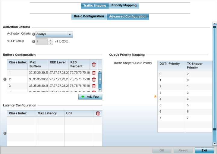
Activation Criteria |
Use the drop-down menu to determine when the traffic shaper is invoked. Options include vrrp-master, cluster-master, rf-domain-manager and Always. A VRRP master responds to ARP requests, forwards packets with a destination link MAC layer address equal to the virtual router MAC layer address, rejects packets addressed to the IP associated with the virtual router and accepts packets addressed to the IP associated with the virtual router. The solitary cluster master is the cluster member elected, using a priority assignment scheme, to provide management configuration and Smart RF data to other cluster members. Cluster requests go through the elected master before dissemination to other cluster members. The RF Domain manager is the elected member capable of storing and provisioning configuration and firmware images for other members of the RF Domain. |
|
VRRP Group |
Set the VRRP group ID from 1 - 255. VRRP groups is only enabled when the Establishment Criteria is set to vrrp-master. |
|
Class Index |
Set a class index from 1 - 4. |
|
Max Buffers |
Set the Max Buffers to specify the queue length limit after which the queue starts to drop packets. Set the maximum queue lengths for packets. The upper length is 400 for access points. |
|
RED Level |
Set the packet queue length for RED. The upper limit is 400 for Access Points. The rate limiter uses the RED (random early detection) algorithm for rate limiting traffic. RED is a queueing technique for congestion avoidance. RED monitors the average queue size and drops or marks packets. If the buffer is near empty, all incoming packets are accepted. When the queue grows, the probability for dropping an incoming packet also grows. When the buffer is full, the probability has reached 1 and all incoming packets are dropped. |
|
RED Percent |
Set a percentage (1 - 100) for RED rate limiting at a percentage of maximum buffers. |
When a new packet arrives it knows how much time to wait in the queue. If a packet takes longer than the latency value, it is dropped. By default latency is not set, so packets remain in queue for long time.
Select Reset to revert to the last saved configuration.
 Print
this page
Print
this page Email this topic
 Feedback
 View PDF
 Download EPUB