The STP (Spanning Tree Protocol), standardized in IEEE 802.1D, is a network protocol that builds a loop-free logical topology for Ethernet networks. The basic function of STP is to prevent bridge loops and the broadcast radiation that results from them. Spanning tree also allows a network design to include backup links to provide fault tolerance if an active link fails.
The Device Overrides screen displays. This screen lists devices within the managed network.
The selected access point's configuration menu displays.
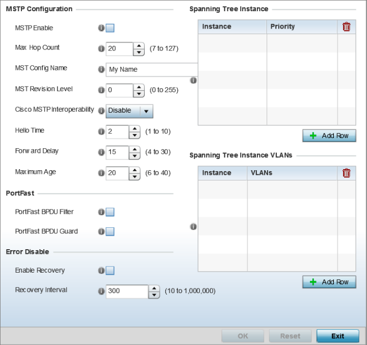
The Spanning Tree configuration screen displays.
|
MSTP Enable |
Select this option to enable MSTP for this profile. MSTP is disabled by default, so if requiring different (groups) of VLANs with the profile supported network segment. |
|
Max Hop Count |
Define the maximum number of hops the BPDU will consider valid in the spanning tree topology. The available range is from 7 - 127. The default setting is 20. |
|
MST Config Name |
Define a 64 character maximum name for the MST region as an identifier. |
|
MST Revision Level |
Set a numeric revision value ID for MST configuration information. Set a value from 0 - 255. The default setting is 0. |
|
Cisco MSTP Interoperability |
Select either the Enable or Disable radio buttons to enable/disable interoperability with Cisco‘s version of MSTP, which is incompatible with standard MSTP. This setting is disabled by default. |
|
Hello Time |
Set a BPDU hello interval from 1 - 10 seconds. BPDUs are exchanged regularly (every 2 seconds by default) and enable supported devices to keep track of network changes and star/stop port forwarding as required. |
|
Forward Delay |
Set the forward delay time from 4 - 30 seconds. When a device is first attached to a port, it does not immediately start to forward data. It first processes BPDUs and determines the network topology. When a host is attached the port always goes into the forwarding state, after a delay of while it goes through the listening and learning states. The time spent in the listening and learning states is defined by the forward delay (15 seconds by default). |
|
Maximum Age |
Use the spinner control to set the maximum time (in seconds) to listen for the root bridge. The root bridge is the spanning tree bridge with the smallest (lowest) bridge ID. Each bridge has a unique ID and a configurable priority number, the bridge ID contains both. The available range is from 6 - 40. The default setting is 20. |
|
PortFast BPDU Filter |
Enable to invoke a BPDU filter for this portfast enabled port. Enabling the BPDU filter feature ensures this port channel does not transmit or receive any BPDUs. BPDUs are exchanged regularly and enable the access point to keep track of network changes and to start and stop port forwarding as required. This option is disabled by default. |
|
PortFast BPDU Guard |
Enable to invoke a BPDU guard for the portfast enabled port. Enabling the BPDU Guard feature means this port will shutdown on receiving a BPDU. Thus, no BPDUs are processed. BPDUs are exchanged regularly and enable the access point to keep track of network changes and to start and stop port forwarding as required. This option is disabled by default. |
|
Enable Recovery |
Select this option to enable a error disable timeout resulting from a BPDU guard. This setting is disabled by default. |
|
Recovery Internal |
Define the recovery interval used to enable disabled ports. The available range is from 10 - 1,000,000 seconds with a default setting of 300. |
Add up to 16 indexes and use the Priority setting to define the bridge priority used to determine the root bridge. The lower the setting defined, the greater the likelihood of becoming the root bridge in the spanning tree topology.
Select Reset to revert to the last saved configuration.
 Print
this page
Print
this page Email this topic
 Feedback
 View PDF
 Download EPUB