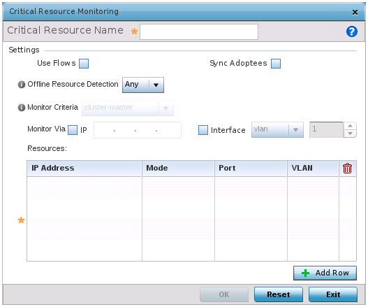
Click Add to add a new critical resource and connection method.
This reduces the amount of traffic on the network. This setting is disabled by default.
This setting is disabled by default.
Options include Any and All. If you select Any, an event is generated when the state of any single critical resource changes. If you select All, an event is generated when the state of all monitored critical resources change.
If you select rf-domain-manager, the current rf-domain manager performs resource monitoring, and the rest of the devices do not. The RF-domain-manager updates any state changes to the rest of the devices in the RF Domain.
With the cluster-master option, the cluster master performs resource monitoring and updates the cluster members with state changes.
With a controller-managed RF Domain, set Monitoring Criteria to All because the controller might not know the VLAN bridged locally by the devices in the RF Domain monitoring DHCP.
If you select VLAN, use the spinner control to define the destination VLAN ID used as the interface for the critical resource.
|
IP Address |
Provide the IP address of the critical resource. This is the address used by the access point to ensure the critical resource is available. Up to four addresses can be defined. |
|
Mode |
Set the ping mode used when the availability of a critical resource is validated. The options are:
|
|
Port |
Provide the port on which the critical resource is available. Use the spinner control to set the port number. |
|
VLAN |
Using the spinner control, define the VLAN on which the critical resource is available. |
Click Reset to revert to the last saved configuration.
 Print
this page
Print
this page Email this topic
 Feedback
 View PDF
 Download EPUB