Wireless Intrusion Protection System (WIPS) protects wireless client and access point radio traffic from attacks and unauthorized access. WIPS provides tools for standards compliance and around-the-clock wireless network security in a distributed environment. WIPS allows administrators to identify and accurately locate attacks, rogue devices and network vulnerabilities in real time and permits both a wired and wireless lockdown of wireless device connections upon acknowledgment of a threat.
In addition to dedicated AirDefense sensors, an access point radio can function as a sensor and upload information to a dedicated WIPS server (external to the access point). Unique WIPS server configurations can be used to ensure a WIPS server configuration is available to support the unique data protection needs of a RF Domain.
WIPS is not supported on a WLAN basis, rather, sensor functionality is supported on the access point radio(s) available to each managed WLAN. When an access point radio is functioning as a WIPS sensor, it is able to scan in sensor mode across all legal channels within the 2.4 and 5.0 GHz band. Sensor support requires an AirDefense WIPS Server on the network. Sensor functionality is not provided by the access point alone. The access point works in conjunction with a dedicated WIPS server.
In addition to WIPS support, sensor functionality has been added for Extreme Networks‘ ExtremeLocation system. locationing system. The ExtremeLocation system for Wi-Fi locationing includes WiNG controllers and access points functioning as sensors. Within the ExtremeLocation architecture, sensors scan for RSSI data on an administrator defined interval and send to a dedicated ExtremeLocation Server resource, as opposed to an ADSP server. The ExtremeLocation Server collects the RSSI data from WiNG sensor devices, and calculates the location of Wi-Fi devices.
To define a WIPS server configuration used with the access point‘s RF Domain:
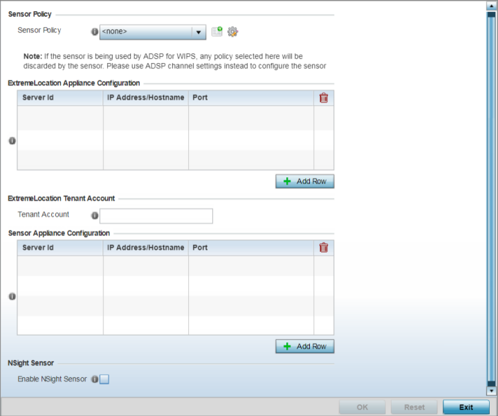

Note
If a dedicated sensor is utilized with ADSP for rogue detection, any sensor policy selected from the Sensor Policy drop-down menu is discarded and not utilized by the sensor. To avoid this situation, use ADSP channel settings exclusively to configure the sensor and not the WiNG interface.Starting with WiNG 7.1.2, AP5XX APs will not use WIPS to collect WiFi packets and BLE (iBeacons and Eddystone) beacons. The information will be collected in the RSSI Collector Table and forwarded to the ExtremeLocation server from the Collector Table.
ExtremeLocation is a highly scalable indoor locationing platform that gathers location-related analytics, such as visitor trends, peak and off-peak times, dwell time, heat-maps, etc. to enable entrepreneurs deeper visibility at a venue. To enable the location tracking system, the ExtremeLocation server should be up and running and the RF Domain configuration should point to the ExtremeLocation server.
| Server Id | Use the spinner control to assign a numerical ID for the
ExtremeLocation server resource. Note: As of now
only one server is supported.
|
| IP Address/Hostname | Provide the hostname of the ExtremeLocation server
resource for receiving RSSI scan data from the AP. Hostname
cannot exceed 64 characters or contain an underscore. Note: Enter the
ExtremeLocation server‘s hostname and not the IP
address, as the IP address is likely to change
periodically in order to balance load across multiple
Location server instances.
|
| Port |
Use the spinner control to specify the port of the ExtremeLocation server resource receiving RSSI scan data. Note:
By default, the ExtremeLocation server is reachable on port 443. |
Note
Ensure that the access points in the RF Domain have at least one radio configured in the 'radio-share' or sensor mode.Note
Starting with WiNG 7.2.0 release, 802. the AP5XX model access points are capable of capturing WPA3 frames in the sensor mode.| Server Id | Use the spinner control to assign a numerical ID for up to three ADSP server resources. The server with the lowest defined ID is the first reached by the controller or service platform. The default ID is 1. |
| IP Address/Hostname | Provide the numerical (non DNS) IP address or hostname of each server used as a ADSP sensor server by RF Domain member devices. A hostname cannot exceed 64 characters or contain an underscore. |
| Port | Use the spinner control to specify the port of each ADSP sensor server utilized by RF member devices. The default port is 443. |
 Print
this page
Print
this page Email this topic
 Feedback
 View PDF
 Download EPUB