To set or override MiNT Protocol related configurations at the device level:
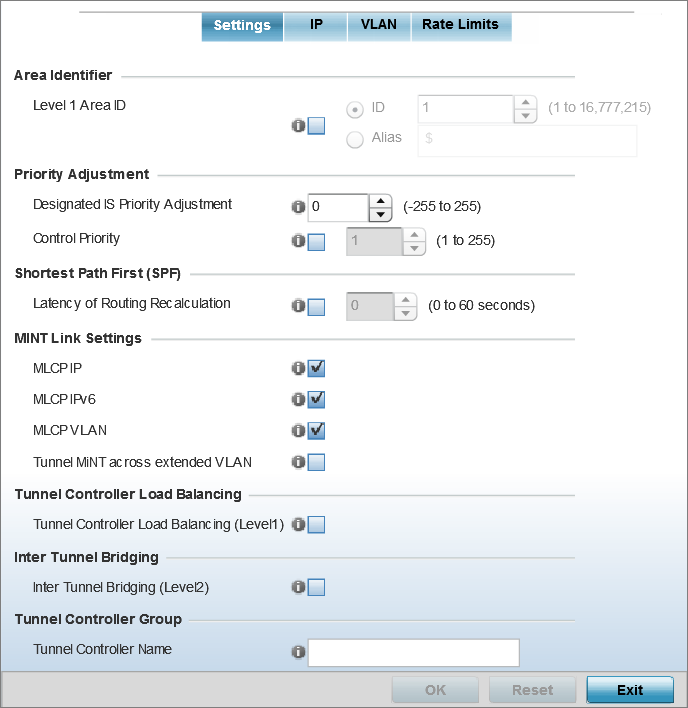
The MiNT Settings tab displays by default.
|
Level 1 Area ID |
Select this option to enable a spinner control for setting the Level 1 Area ID from 1 - 16,777,215. The default value is disabled. Alternatively, provide an alias by selecting the Alias option and adding the alias name to this field. |
|
Designated IS Priority Adjustment |
Use the spinner control to set a Designated IS Priority Adjustment setting from -255 - +255. This is the value added to the base level DIS priority to influence the DIS (Designated IS) election. A value of +1 or greater increases DISiness. The default setting is 0. |
|
Control Priority |
Select to set the priority of this device with respect to others, within the network, in being selected as the Level 2 router. Higher the value, higher is the chances of the device of becoming the Level 2 router. Note:
This option is disbaled by default. |
The option is disabled by default.
|
MLCP IP |
Select this option to enable MLCP (MiNT Link Creation Protocol) by IP Address. MLCP is used to create a UDP/IP link from the device to a neighbor. The neighboring device can be another AP. Note:
This option is enabled by default. |
|
MLCP IPv6 |
Select this option to enable MLCP by IPv6 Address. MLCP by IPv6 is used to create one UDP/IP link from the device to a neighbor. The neighboring device does not need to be a virtual controller; it can be an standalone access point. Note:
This option is enabled by default. |
|
MLCP VLAN |
Select this option to enable MiNT MLCP by VLAN. MLCP is used to create one VLAN link from the device to a neighbor. The neighboring device can be another AP. Note:
This option is enabled by default. |
|
Tunnel MiNT across extended VLAN |
Select this option to tunnel MiNT protocol packets across an extended VLAN. Note:
This option is disabled by default. |
This option is disabled by default.
This option is disabled by default.
This is specific for this access point only.
Click Reset to revert to the last saved configuration.
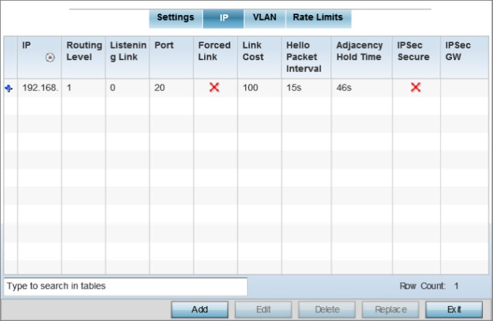
The IP tab displays the IP address, Routing Level, Listening Link, Port, Forced Link, Link Cost, Hello Packet Interval, Adjacency Hold Time, IPSec Secure, and IPSec GW information that managed devices use to communicate securely with each other.
The MiNT IP configuration screen displays.
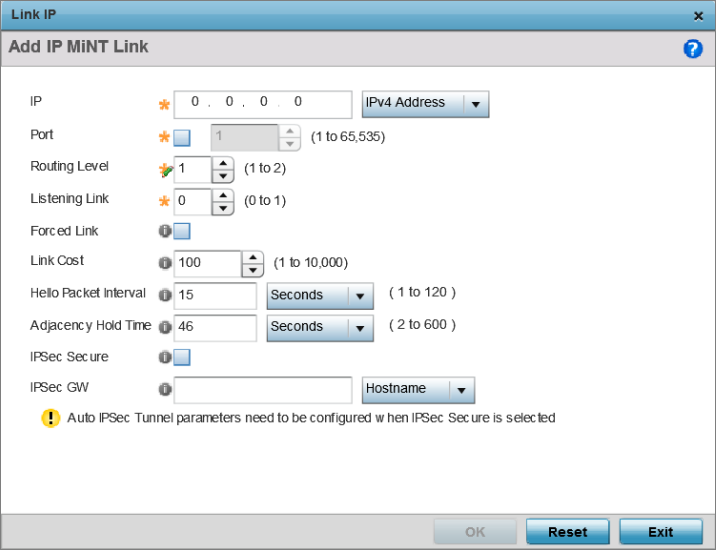
The add/edit MiNT IP configuration window displays.
|
IP |
Define or override the IP address used by peer access points for interoperation when supporting the MiNT protocol. |
|
Port |
To specify a custom port for MiNT links, select this option and use the spinner control to define or override the port number from 1 - 65,535. |
|
Routing Level |
Define or override a routing level of either 1 or 2. |
|
Listening Link |
Specify a listening link of either 0 or 1. UDP/IP links can be created by configuring a matching pair of links, one on each end point. However, that is error prone and does not scale. So UDP/IP links can also listen (in the TCP sense), and dynamically create connected UDP/IP links when contacted. |
|
Forced Link |
Select this option to specify the MiNT link as a forced link. Note:
This setting is disabled by default. |
|
Link Cost |
Define or override a link cost from 1 - 10,000. The default value is 100. |
|
Hello Packet Interval |
Set or override an interval in either seconds (1 - 120) or minutes (1 - 2) for the transmission of hello packets. Note:
The default interval is 15 seconds. |
|
Adjacency Hold Time |
Set or override a hold time interval in either seconds (2 - 600) or minutes (1 - 10) for the transmission of hello packets. The default interval is 46 seconds. |
|
IPSec Secure |
Select this option to use a secure link for IPSec traffic. This setting is disabled by default. When this option is enabled, both the header and the traffic payload are encrypted. |
|
IPSec GW |
Define either an IP address or hostname for the IPSec gateway. |
Click Reset to revert to the last saved configuration.
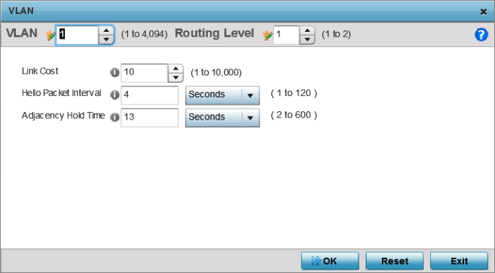
The MiNT VLAN configuration screen displays. The VLAN tab displays the VLAN, Routing Level, Link Cost, Hello Packet Interval, and Adjacency Hold Time managed devices use to communicate securely with each another.
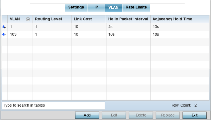

Note
If creating a mesh link between two access points in Standalone AP mode, you will need to ensure a VLAN is available to provide the necessary MiNT link between the two Standalone APs.
|
VLAN |
Define a VLAN ID from 1 - 4094 used by peer controllers for interoperation when supporting the MiNT protocol. |
|
Routing Level |
Define or override a routing level of either 1 or 2. |
|
Link Cost |
Use the spinner control to define or override a link cost from 1 - 10,000. Note:
The default value is 10. |
|
Hello Packet Interval |
Set or override an interval in either seconds (1 - 120) or minutes (1 - 2) for the transmission of hello packets. Note:
The default interval is 4 seconds. |
|
Adjacency Hold Time |
Set or override a hold time interval in either seconds (2 - 600) or minutes (1 - 10) for the transmission of hello packets. Note:
p |
Click Reset to revert to the last saved configuration.
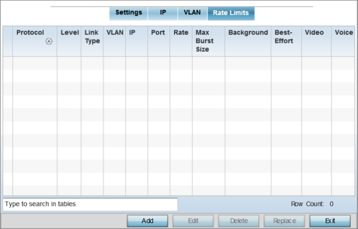
The Rate Limits tab displays the Protocol, Level, Link Type, VLAN, IP, Port, Rate, Max Burst Size, Background, Best-Effort, Video, and Voice rate limiting parameters for each of the configured device.
Excessive traffic can cause performance issues on an extended VLAN. Excessive traffic can be caused by numerous sources including network loops, faulty devices, or malicious software such as a worm or virus that has infected on one or more devices. Rate limiting reduces the maximum rate sent or received per wireless client. It prevents any single user from overwhelming the wireless network. It can also provide differential service for service providers. Uplink and downlink rate limits are usually configured on a RADIUS server using vendor specific attributes. Rate limits are extracted from the RADIUS server‘s response. When such attributes are not present, the settings defined on the controller, service platform, or access point are applied. An administrator can set separate QoS rate limit configurations for data types transmitted from the network (upstream) and data transmitted from a wireless clients back to associated radios (downstream). Existing rate limit configurations display along with their virtual connection protocols and data traffic QoS customizations.
|
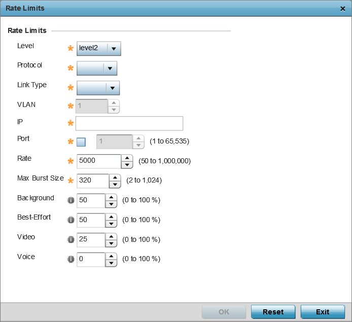
Level |
Select level2 to apply rate limiting for all links on level 2. |
|
Protocol |
Select either mlcp or link as this configuration‘s rate limit protocol. MLCP creates a UDP/IP link from the device to a neighbor. The neighboring device does not need to be a controller or service platform; it can be an access point with a path to the controller or service platform. Select link to rate limit using statically configured MiNT links. |
|
Link Type |
Select either VLAN, to configure a rate limit configuration on a specific virtual LAN, or IP to set rate limits on a static IP address/port configuration. |
|
VLAN |
When Protocol is set to link and Link Type is set to VLAN, select a virtual LAN from 1 - 4094 to refine the rate limiting configuration to a specific VLAN. |
|
IP |
When Protocol is set to link and Link Type is set to VLAN, enter the IP address as the network target for rate limiting. |
|
Port |
When Protocol is set to link and Link Type is set to VLAN, set the virtual port (1 - 65,535) used for rate limiting traffic. |
|
Rate |
Define a rate limit between 50 - 1,000,000 kbps. This limit constitutes a threshold for the maximum the number of packets transmitted or received (from all access categories). Traffic that exceeds the defined rate is dropped and a log message is generated. Note:
The default setting is 5000 kbps. |
|
Max Burst Size |
Set the maximum burst size from 0 - 1024 kb. The smaller the burst, the less likely the upstream packet transmission will result in congestion for the WLAN‘s client destinations. By trending the typical number of ARP, broadcast, multicast and unknown unicast packets over a period of time, the average rate for each access category can be obtained. Once a baseline is obtained, administrators should add a 10% margin (minimally) to allow for traffic bursts. Note:
The default burst size is 320 kbytes. |
|
Background |
Configure the random early detection threshold (as a percentage) for low priority background traffic. Background packets are dropped and a log message generated if the rate exceeds the set value. Background traffic consumes the least bandwidth of any access category, so this value can be set to a lower value once a general upstream rate is known by the network administrator (using a time trend analysis). Note:
The default setting is 50%. |
|
Best-Effort |
Configure the random early detection threshold (as a percentage) for low priority best effort traffic. Best-effort packets are dropped and a log message generated if the rate exceeds the set value. Best effort traffic consumes little bandwidth, so this value can be set to a lower value once a general upstream rate is known by the network administrator (using a time trend analysis). Note:
The default setting is 50%. |
|
Video |
Configure the random early detection threshold (as a percentage) for high priority video traffic. Video packets are dropped and a log message generated if the rate exceeds the set value. Video traffic consumes significant bandwidth, so this value can be set to a higher value once a general upstream rate is known by the network administrator (using a time trend analysis). Note:
The default setting is 25%. |
|
Voice |
Configure the random early detection threshold (as a percentage) for high priority voice traffic. Voice packets are dropped and a log message generated if the rate exceeds the set value. Voice applications consume significant bandwidth, so this value can be set to a higher value once a general upstream rate is known by the network administrator (using a time trend analysis). Note:
The default setting is 0%. |
Click Reset to revert to the last saved configuration.
 Print
this page
Print
this page Email this topic
 Feedback
 View PDF
 Download EPUB