A VLAN is separately administrated virtual network within the same physical managed network. VLANs are broadcast domains defined to allow control of broadcast, multicast, unicast, and unknown unicast within a Layer 2 device.
For example, say several computers are used in conference room X and some in conference Y. The systems in conference room X can communicate with one another, but not with the systems in conference room Y. The creation of a VLAN enables the systems in conference rooms X and Y to communicate with one another even though they are on separate physical subnets. The systems in conference rooms X and Y are managed by the same single device, but ignore the systems that aren't using same VLAN ID.
Administrators often need to route traffic to interoperate between different VLANs. Bridging VLANs are only for non-routable traffic, like tagged VLAN frames destined to some other device which will untag it. When a data frame is received on a port, the VLAN bridge determines the associated VLAN based on the port of reception. Using forwarding database information, the Bridge VLAN forwards the data frame on the appropriate port(s). VLAN's are useful to set separate networks to isolate some computers from others, without actually having to have separate cabling and Ethernet switches. Controllers and service platforms can do this on their own, without the need to know what VLAN it's on (this is called port-based VLAN, since it's assigned by port). Another common use is to put specialized devices like VoIP Phones on a separate network for easier configuration, administration, security or service quality.
To define a bridge VLAN configuration:
Go to .
The Profile screen displays. This screen lists access point profiles.
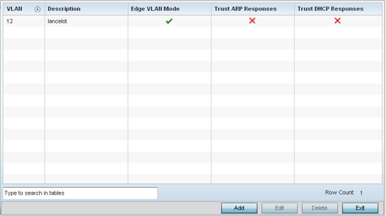
Review the following VLAN configuration parameters to determine whether an update is warranted:
| VLAN |
Lists the numerical identifier defined for the Bridge VLAN when initially created. The available range is from 1 - 4095. This value cannot be modified during the edit process. |
|
Description |
Lists a description of the VLAN assigned when it was created or modified. The description should be unique to the VLAN's specific configuration and help differentiate it from other VLANs with similar configurations. |
|
Edge VLAN Mode |
Defines whether the VLAN is currently in edge VLAN mode. A green checkmark defines the VLAN as extended. An edge VLAN is the VLAN where hosts are connected. For example, if VLAN 10 is defined with wireless clients, and VLAN 20 is where the default gateway resides, VLAN 10 should be marked as an edge VLAN and VLAN 20 shouldn't. When defining a VLAN as an edge VLAN, the firewall enforces additional checks on hosts in that VLAN. For example, a host cannot move from an edge VLAN to another VLAN and still keep firewall flows active. |
|
Trust ARP Response |
When ARP trust is enabled, a green checkmark displays. When disabled, a red "X" displays. Trusted ARP packets are used to update the IP-MAC Table to prevent IP spoof and arp-cache poisoning attacks. |
|
Trust DHCP Responses |
When DHCP trust is enabled, a green checkmark displays. When disabled, a red "X" displays. When enabled, DHCP packets from a DHCP server are considered trusted and permissible. DHCP packets are used to update the DHCP Snoop Table to prevent IP spoof attacks. |
Select Add to define a new bridge VLAN configuration, Edit to modify an existing bridge VLAN configuration or Delete to remove a VLAN configuration.
 Print
this page
Print
this page Email this topic
 Feedback
 View PDF
 Download EPUB