GRE (Generic routing encapsulation) tunneling can be configured to bridge Ethernet packets between WLANs and a remote WLAN gateway over a GRE tunnel. The tunneling of 802.3 packets using GRE is an alternative to MiNT or L2TPv3. Related features like ACLs for extended VLANs are still available using layer 2 tunneling over GRE.
Using GRE, access points map one or more VLANs to a tunnel. The remote endpoint is a user-configured WLAN gateway IP address, with an optional secondary IP address should connectivity to the primary GRE peer be lost. VLAN traffic is expected in both directions in the GRE tunnel. A WLAN mapped to these VLANs can be either open or secure. Secure WLANs require authentication to a remote RADIUS server available within your deployment using standard RADIUS protocols. access points can reach both the GRE peer as well as the RADIUS server using IPv4.
To override an access point's GRE tunnel configuration.
The Device Overrides screen displays. This screen lists devices within the managed network.
The selected access point's configuration menu displays.
The GRE Tunnel screen displays. This screen lists existing GRE tunnel configurations.
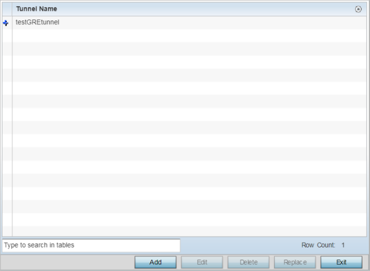
You can add new tunnels or delete existing tunnels.
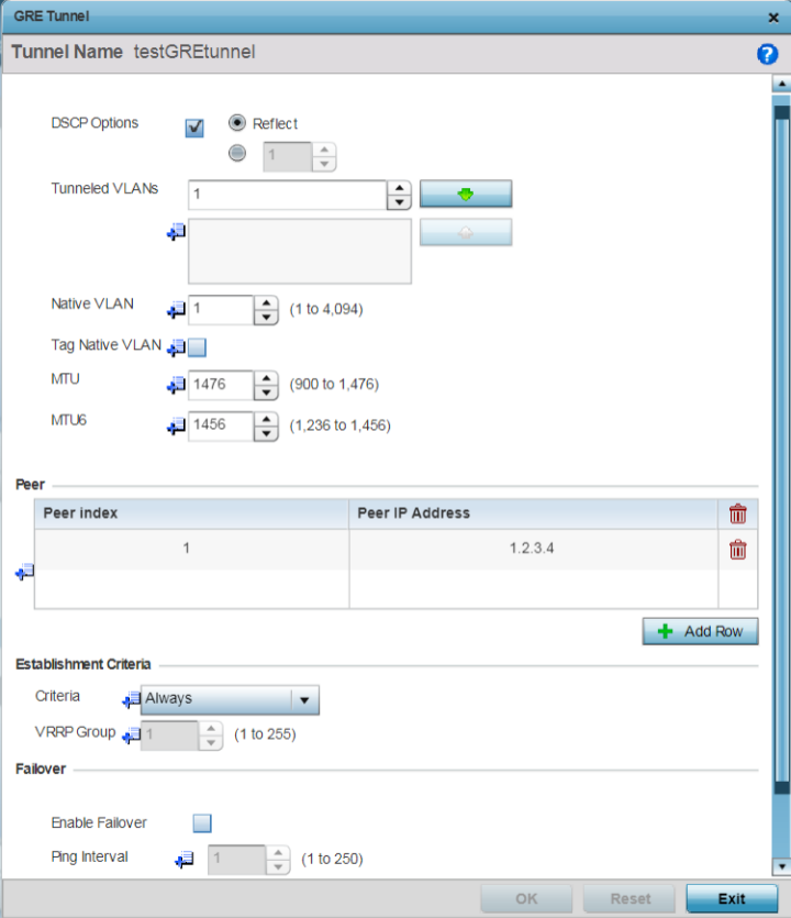
The GRE tunnel configuration screen displays.
|
DSCP Options |
Use the spinner control to set the tunnel DSCP / 802.1q priority value from encapsulated packets to the outer packet IPv4 header. |
|
Tunneled VLANs |
Define the VLAN connected clients use to route GRE tunneled traffic within their respective WLANs. |
|
Native VLAN |
Set a numerical VLAN ID (1 - 4094) for the native VLAN. The native VLAN allows an Ethernet device to associate untagged frames to a VLAN when no 802.1Q frame is included in the frame. Additionally, the native VLAN is the VLAN untagged traffic is directed over when using a port in trunk mode. |
|
Tag Native VLAN |
Select this option to tag the native VLAN. The IEEE 802.1Q specification is supported for tagging frames and coordinating VLANs between devices. IEEE 802.1Q adds four bytes to each frame identifying the VLAN ID for upstream devices that the frame belongs. If the upstream Ethernet device does not support IEEE 802.1Q tagging, it does not interpret the tagged frames. When VLAN tagging is required between devices, both devices must support tagging and be configured to accept tagged VLANs. When a frame is tagged, the 12 bit frame VLAN ID is added to the 802.1Q header so upstream Ethernet devices know which VLAN ID the frame belongs to. The device reads the 12 bit VLAN ID and forwards the frame to the appropriate VLAN. When a frame is received with no 802.1Q header, the upstream device classifies the frame using the default or native VLAN assigned to the Trunk port. The native VLAN allows an Ethernet device to associate untagged frames to a VLAN when no 802.1Q frame is included in the frame. This feature is disabled by default. |
The Peer table lists the credentials of the GRE tunnel end points.
|
Peer Index |
Assign a numeric index to each peer to help differentiate tunnel end points. |
|
Peer IP Address |
Define the IP address of the added GRE peer to serve as a network address identifier. |
|
Criteria |
Specify the establishment criteria for creating a GRE
tunnel. In a multicontroller within a RF domain, it‘s
always the master node with which the tunnel is
established. Dependimg on which of the following options
is selected, the GRE is established:
|
|
VRRP Group |
Set the VRRP group ID only enabled when the Establishment Criteria is set to vrrp-master. A virtual router redundancy group nables the creation of a group of routers as a default gateway for redundancy. Clients can point to the IP address of the VRRP virtual router as their default gateway and utilize a different group member if a master becomes unavailable. |
|
Enable Failover |
Select this option to periodically ping the primary gateway to assess its availability for failover support. |
|
Ping Interval |
Set the duration between two successive pings to the gateway. Define this value in seconds from 0 - 86,400. |
|
Number of Retries |
Set the number of retry ping opportunities before the session is terminated. |
Select Reset to revert to the last saved configuration.
 Print
this page
Print
this page Email this topic
 Feedback
 View PDF
 Download EPUB