To override a radio's advanced settings:
The selected radio interface's advanced settings screen displays:
|
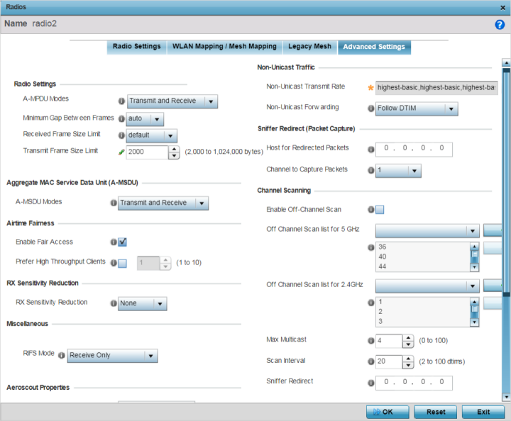
A-MPDU Modes |
Specify the A-MPDU mode. Options include Transmit Only, Receive Only, Transmit and Receive, and None. The default value is Transmit and Receive. Using the default value, long frames can be both sent and received (up to 64 KB). When this option is enabled, define a transmit limit, a receive limit, or both. |
|
Minimum Gap Between Frames |
Use the drop-down menu to define, in
microseconds, the minimum gap between
consecutive A-MPDU frames. The options
include:
|
|
Received Frame Size Limit |
If the A-MPDU mode is set to Receive Only or Transmit and Receive, use this option to define an advertised maximum limit for received A-MPDU aggregated frame size. The options include:
|
|
Transmit Frame Size Limit |
If the A-MPDU mode is set to Transmit Only or Transmit and Receive, use the spinner control to set limit on transmitted A-MPDU aggregated frame size. The range depends on the AP type and the radio selected. For 802.11ac capable APs,
the range is as follows:
Note:
The WiNG 802.11ac capable APs are: AP7522, AP7532, AP7562, AP7602, AP7612, AP7632, AP7662, AP8432, and AP8533. For non 802.11ac capable
APs the range is as follows:
|
Available modes are Receive Only and Transmit and Receive. Use Transmit and Receive to send and receive frames up to 4 KB. The buffer limit is not configurable. Transmit and Receive is the default value.
|
Enable Fair Access |
Select to enable fair access to all peer devices. |
|
Prefer High Throughput Clients |
Select to prefer clients with higher throughput (802.11n clients) over clients with slower throughput (802.11 a/b/g) clients. Use the spinner control to set a weight for the higher throughput clients. |
This threshold determines the RSSI (in dBm) at which the radio acknowledges the SOP (Start of Packet) frames received from the client, and begins to demodulate and decode the packets.
In highly dense environments, or single-channel networks, having two or more radios sharing a channel, CCI (co-channel interference) adversely impacts network performance. By setting this threshold, you can control the radio‘s receive sensitivity to interference and noise, thereby reducing the impact of CCI. You are basically configuring the AP to not decode packets that have a signal strength below the specified threshold level.
The available rx-sensitivity-reduction threshold levels are: High, Low, Medium and None. Set the threshold level as High, to force your radio to ignore all traffic having a signal strength below the high threshold level value. This results in fewer traffic interruptions due to collision and Wi-Fi interference. Note, the default setting is None.
|
802.11 Bands |
High Threshold |
Medium Threshold |
Low Threshold |
|---|---|---|---|
|
2.4 GHz |
-79 dBm |
-82 dBm |
-85 dBm |
|
5 GHz |
-76 dBm |
-78 dBm |
-80 dBm |

Note
This feature is supported only on the following access points: AP-7522, AP 7532, AP 7562, AP-8432, AP-8533
|
RIFS Mode |
Interframe spacing is an interval between two consecutive Ethernet frames to enable a brief recovery between packets and allow target devices to prepare for the reception of the next packet. Use this option to specify the interframe spacing
settings:
|
|
Forward |
Select this option to enable forwarding of Aeroscout packets. |
|
MAC to be forwarded |
Enter the MAC address that is incorporated in the Aeroscout packets that are forwarded. |
|
Forwarding Host |
Specify the IP address of the host to which Ekahau packets are forwarded. |
|
Forwarding Port |
Set the Ekahau forwarding port number. |
|
MAC to be forwarded |
Enter the MAC address that is incorporated in the Ekahau packets that are forwarded. |
|
Non-Unicast Transmit Rate |
Use the Select drop-down menu to launch a sub-screen to define the data rate for broadcast and multicast frame transmissions. If you are not using the same rate for each BSSID, seven different rates are available – each with a separate menu. |
|
Non-Unicast Forwarding |
Define whether client broadcast and multicast packets should always follow DTIM, or only follow DTIM when using Power Save Aware mode. The default setting is Follow DTIM. |
|
Host for Redirected Packets |
If packets are redirected from a controller or service platform‘s connected access point radio, specify the IP address of a resource (additional host system) used to capture the redirected packets. This address is the numerical (non DNS) address of the host used to capture the redirected packets. |
|
Channel to Capture Packets |
Specify the channel used to capture redirected packets. The default value is channel 1. |
|
Enable Off-Channel Scan |
Select to enable scan across all channels using this radio. Channel scans use access point resources and can be time consuming, so only enable when your sure the radio can afford the bandwidth be directed toward the channel scan and does not negatively impact client support. This option is disabled by default. |
|
Off Channel Scan list for 5GHz |
Select the list of channels for off-channel scans using the access point's 5GHz radio. Restricting off-channel scans to specific channels frees bandwidth otherwise utilized for scanning across all the channels in the 5GHz radio band. |
|
Off Channel Scan list for 2.4GHz |
Select the list of channels for off-channel scans using the access point's 2.4GHz radio. Restricting off-channel scans to specific channels frees bandwidth otherwise utilized for scanning across all the channels in the 2.4GHz radio band. |
|
Max Multicast |
Set the maximum number (from 0 - 100) of multicast/broadcast messages used to perform off-channel scanning. The default setting is 4. |
|
Scan Interval |
Set the interval (from 2 - 100 dtims) between off-channel scans. The default setting is 20 dtims. |
|
Sniffer Redirect |
Specify the IP address of the host to which captured off-channel scan packets are redirected. |
Click Reset to revert to the last saved configuration.
 Print
this page
Print
this page Email this topic
 Feedback
 View PDF
 Download EPUB