To define or override the L2TPv3 tunnel settings:
The L2TPv3 Tunnel Settings configuration screen displays.
|
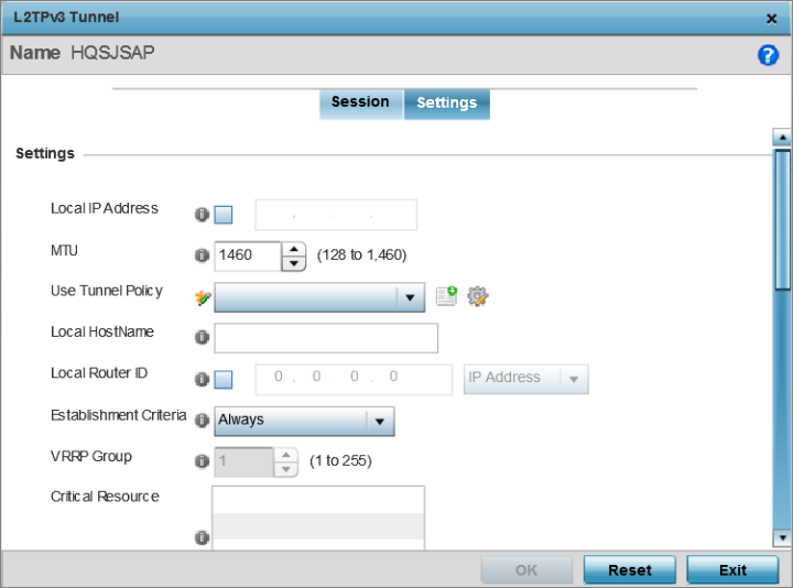
Local IP Address |
Enter the IP address assigned as the local tunnel end point address, not the interface IP address. This IP is used as the tunnel source IP address. If this parameter is not specified, the source IP address is chosen automatically based on the tunnel peer IP address. This parameter is applicable when establishing the tunnel and responding to incoming tunnel create requests. |
|
MTU |
Set the MTU. The MTU is the size (in bytes) of the largest protocol data unit the layer can pass between tunnel peers. Define a MTU between 128 - 1,460 bytes. The default setting is 1,460. A larger MTU means processing fewer packets for the same amount of data. |
|
Use Tunnel Policy |
Select the L2TPv3 tunnel policy. The policy consists of user defined values for protocol specific parameters which can be used with different tunnels. If none is available a new policy can be created or an existing one can be modified. For more information, refer to L2TP V3 Configuration. |
|
Local Hostname |
Provide the tunnel specific hostname used by this tunnel. This is the hostname advertised in tunnel establishment messages. |
|
Local Router ID |
Specify the router ID sent in tunnel establishment messages with a potential peer device. |
|
Establishment Criteria |
Configure establishment criteria for creating a tunnel
between the device and the NOC. This criteria ensures
only one tunnel is created between two sites where the
tunnel is established between the vrrp-master/cluster
master/rfdomain manager at the remote site and the
controller at the NOC. The tunnel is created based on
the role of the remote peer.
In all the above cases, if the local device goes offline for any reason, the tunnel is brought down. |
|
VRRP Group |
This field is enabled only when the establishment criteria is set to vrrp-master. Use the spinner to select the VRRP group. |
|
Critical Resource |
Enter the critical resources required for creating and maintaining a L2TPV3 tunnel. A tunnel is only established when all critical resources for the tunnel to be operational are available at the time when the tunnel is created. If any one of the listed critical resources goes down, the tunnel is disabled. When a tunnel is established, the listed critical resources are checked for availability. Tunnel establishment is started if the critical resources are available. Similarly, for incoming tunnel termination requests, listed critical resources are checked and tunnel terminations are only allowed when the critical resources are available. For more information on managing critical resources, see Profile Overrides - List of Critical Resources . |
Rate limiting manages the maximum rate sent to or received from L2TPv3 tunnel members.
|
Session Name |
Use the drop-down menu to select the tunnel session that will have the direction, burst size and traffic rate settings applied. |
|
Direction |
Select the direction for L2TPv3 tunnel traffic rate limiting. Egress traffic is outbound L2TPv3 tunnel data coming to the controller, service platform or access point. Ingress traffic is inbound L2TPv3 tunnel data coming to the controller, service platform or access point. |
|
Max Burst Size |
Set the maximum burst size for egress or ingress traffic rate limiting (depending on which direction is selected) on a L2TPv3 tunnel. Set a maximum burst size between 2 - 1024 kbytes. The smaller the burst, the less likely the upstream packet transmission will result in congestion for L2TPv3 tunnel traffic. The default setting is 320 bytes. |
|
Rate |
Set the data rate (from 50 - 1,000,000 kbps) for egress or ingress traffic rate limiting (depending on which direction is selected) for an L2TPv3 tunnel. The default setting is 5000 kbps. |
|
Background |
Set the random early detection threshold in % for background traffic. Set a value from 1 - 100%. The default is 50%. |
|
Best-Effort |
Set the random early detection threshold in % for best-effort traffic. Set a value from 1 - 100%. The default is 50%. |
|
Video |
Set the random early detection threshold in % for video traffic. Set a value from 1 - 100%. The default is 25%. |
|
Voice |
Set the random early detection threshold in % for voice traffic. Set a value from 1 - 100%. The default is 25%. |
|
Peer ID |
Define the primary peer ID used to set the primary and secondary peer for tunnel fail over. If the peer is not specified, tunnel establishment does not occur. However, if a peer tries to establish a tunnel with this access point, it creates the tunnel if the hostname and/or Router ID matches. |
|
Router ID |
Specify the router ID sent in tunnel establishment messages with this specific peer. |
|
Hostname |
Assign the peer a hostname that can be used as matching criteria in the tunnel establishment process. |
|
Encapsulation |
Select either IP or UDP as the peer encapsulation protocol. UDP uses a simple transmission model without implicit handshakes. The default setting is IP. |
|
Peer IP Address |
Select this option to enter the numeric IP address used as the destination peer address for tunnel establishment. |
|
UDP Port |
If UDP encapsulation is selected, use the spinner control to define the UDP encapsulation port. |
|
IPSec Secure |
Enable this option to enable security on the connection between the access point and the Virtual Controller. |
|
IPSec Gateway |
Specify the IP Address of the IPSec Secure Gateway. |
|
Enable |
When enabled, the device starts sending tunnel requests on both peers, and in turn, establishes the tunnel on both peers. If disabled, tunnel establishment only occurs on one peer, with failover and other functionality the same as legacy behavior. If fast failover is enabled after establishing a single tunnel the establishment is restarted with two peers. One tunnel is defined as active and the other as standby. Both tunnels perform connection health checkups with individual hello intervals. This setting is disabled by default. |
|
Enable Aggressive Mode |
When enabled, tunnel initiation hello requests are set to zero. For failure detections, hello attempts are not retried, regardless of defined retry attempts. This setting is disabled by default. |
Click Reset to revert the screen to its last saved configuration.
 Print
this page
Print
this page Email this topic
 Feedback
 View PDF
 Download EPUB