Profile Overrides - Spanning Tree Configuration (AP Only)

To override the spanning tree configuration:
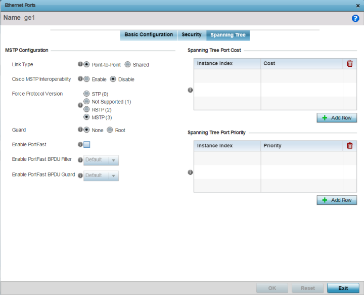
  1. Select the Spanning Tree tab.
    The selected Ethernet Port's Spanning Tree screen displays.
    Click to expand in new window
    Profile Overrides - Interface - Ethernet Ports - Spanning Tree
    GUID-0D3E81F2-7943-457F-9233-AB9910EADA9C-low.png
  2. Set the following MSTP Configuration settings:

    Link Type

    Set the link type for this port:
    • Point-to-Point - Select to treat the port as connected to a point-to-point link

    • Shared - Select to treat the port as shared between multiple devices

    An example of a Point-to-Point connection is a port that is connected to an access point.

    Cisco MSTP Interoperability

    Use to Enable or Disable interoperability with Cisco‘s version of MSTP over the port. Cisco's version of MSTP is incompatible with standard MSTP.

    Force Protocol Version

    Set the Spanning Tree Protocol to enforce. The options are:
    • STP - Enforces the standard Spanning Tree Protocol.

      STP (Spanning Tree Protocol) (IEEE 802.1D standard) configures a meshed network for robustness by eliminating loops within the network and calculating and storing alternate paths to provide fault tolerance.

      As the port comes up and STP calculation takes place, the port is set to Blocked state. In this state, no traffic can pass through the port. Since STP calculations take up to a minute to complete, the port is not operational thereby effecting the network behind the port. When the STP calculation is complete, the port‘s state is changed to Forwarding and traffic is allowed.

    • RSTP - Enforces Rapid Spanning Tree Protocol.

      RSTP (Rapid Spanning Tree Protocol) (IEEE 802.1w standard) is an evolution over the standard STP. The primary aim is to reduce the time taken to respond to topology changes while being backward compatible with STP. PortFast enables quickly changing the state of a port from Blocked to Forwarding to enable the port to allow traffic while the STP calculation happens.

    • MSTP - Enforces Multiple Spanning Tree Protocol. This is the default setting.

      MSTP (Multiple Spanning Tree Protocol) provides an extension to RSTP to optimize the usefulness of VLANs. MSTOP allows for a separate spanning tree for each VLAN group, and blocks all but one of the possible alternate paths within each spanning tree topology.

      If there is only one VLAN in the access point managed network, a single spanning tree works fine. However, if the network contains more than one VLAN, the network topology defined by single STP would work, but it is possible to make better use of the alternate paths available by using an alternate spanning tree for different VLANs or groups of VLANs.

      An MSTP supported deployment uses multiple MST regions with multiple MSTIs (MST instances). Multiple regions and other STP bridges are interconnected using one single common spanning tree (CST). MSTP includes all of its spanning tree information in a single Bridge Protocol Data Unit (BPDU) format. BPDUs are used to exchange information bridge IDs and root path costs. Not only does this reduce the number of BPDUs required to communicate spanning tree information for each VLAN, but it also ensures backward compatibility with RSTP.

      MSTP encodes additional region information after the standard RSTP BPDU as well as a number of MSTI messages. Each MSTI message conveys spanning tree information for each instance. Each instance can be assigned a number of configured VLANs. The frames assigned to these VLANs operate in this spanning tree instance whenever they are inside the MST region. To avoid conveying their entire VLAN to spanning tree mapping in each BPDU, the access point encodes an MD5 digest of their VLAN to an instance table in the MSTP BPDU. This digest is used by other MSTP supported devices to determine if the neighboring device is in the same MST region as itself.

    • Not Supported - Select to disable spanning tree protocol for this interface.

    Guard

    Select Root radio to enable root guard – a mechanism to prevent election of roots other than those designated as roots in a network. When this port receives a better (superior) BPDU, the port state becomes Blocked. It retains this state till the port no longer receives the better (superior) BPDU and then the state is changed to Forwarding. Select Root to enable this feature. Select None to disable this feature.

  3. Set the following PortFast configuration:

    Enable PortFast

    PortFast reduces the time taken for a port to complete STP. PortFast must only be enabled on ports on the wireless controller which are directly connected to a server/workstation and not to another hub or controller. PortFast can be left unconfigured on the access point.

    Select this option to enable drop-down menus for both the Enable PortFast BPDU Filter and Enable PortFast BPDU Guard options. This setting is disabled by default.

    Enable PortFast BPDU Filter

    MSTP BPDUs are messages exchanged when controllers gather information about the network topology during STP scan. When enabled, PortFast enabled ports do not transmit or receive BPDU messages. Default sets the PortFast BPDU Filter value to the bridge's BPDU filter value.

    Select Enable to invoke a BPDU filter for this PortFast enabled port channel. Set Disable to disable this feature.

    Enable PortFast BPDU Guard

    When set to Enable, PortFast enabled ports are forced to shut down when they receive BPDU messages. When set to Default sets the PortFast BPDU Guard value to the bridge's BPDU guard value. Set Disable to disable this feature.

  4. Refer to the Spanning Tree Port Cost table.

    Define or override an Instance Index using the spinner control, and set its corresponding cost in the Cost column.

    This is the cost for a packet to traverse the current network segment. The cost of a path is the sum of all costs of traversal from the source to the destination. The default rule for the cost of a network segment is, the faster the media, the lower the cost.

    Select + Add Row as needed to include additional indexes.

  5. Refer to the Spanning Tree Port Priority table.

    Define or override an Instance Index using the spinner control, and set its corresponding priority in the Priority column.

    This is the priority for this port becoming a designated root. The default rule is, the lower this value, the higher the chance that the port is assigned as a designated root.

    Select + Add Row as needed to include additional indexes.

  6. Click OK to save the changes and overrides made to the Ethernet port's Spanning Tree configuration.

    Click Reset to revert to the last saved configuration.