You must first configure a CIST before configuring any MSTIs in the region. You cannot delete or disable a CIST if any of the MSTIs are active in the system.
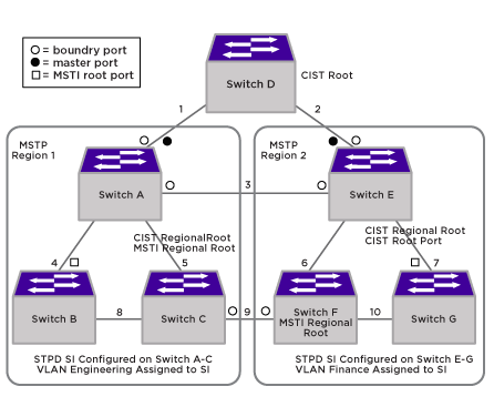
MSTP Configuration Example is an example with multiple STPDs that can benefit from MSTP. In this example, we have two MSTP regions that connect to each other and one external 802.1w bridge.
For MSTP to work, complete the following steps on all switches in Region 1 and Region 2:

Note
If you do not explicitly configure the VLAN ID in your MSTP deployment, use the show vlan command to see the internal VLAN ID automatically assigned by the switch.Note
You can configure only one MSTP region on the switch at any given time.On the external switch (the switch that is not in a region):
Note
In the following sample configurations, any lines marked (Default) represent default settings and do not need to be explicitly configured. STPD s0 already exists on the switch.In the following example, the commands configure Switch A in Region 1 for MSTP. Use the same commands to configure each switch in Region 1:
create vlan engineering
configure vlan engineering tag 2
configure vlan engineering add port 2-3 tagged
configure mstp region region1
create stpd s0 (Default)
disable stpd s0 auto-bind vlan Default
configure stpd s0 mode mstp cist (Default)
configure stpd s0 priority 32768 (Default)
enable stpd s0 (Default)
create stpd s1
configure stpd s1 mode mstp msti 1
configure stpd s1 priority 32768 (Default)
enable stpd s1 auto-bind vlan engineering
configure stpd s0 ports link-type point-to-point 2-3
enable stpd s1
In the following example, the commands configure Switch E in Region 2 for MSTP. Use the same commands to configure each switch in Region 2:
create vlan finance
configure vlan finance tag 2
configure vlan finance add port 2-3 tagged
configure mstp region region2
create stpd s0 (Default)
configure stpd s0 mode mstp cist (Default)
configure stpd s0 priority 32768 (Default)
disable stpd s0 auto-bind vlan Default
enable stpd s0 (Default)
create stpd s1
configure stpd s1 mode mstp msti 1
configure stpd s1 priority 32768 (Default)
enable stpd s1 auto-bind vlan finance
configure stpd s0 ports link-type point-to-point 2-3
In the following example, the commands configure switch D, the external switch. Switch D becomes the CIST root bridge:
create stpd s0 (Default)
disable stpd s0
configure stpd s0 mode dot1w
configure stpd s0 priority 28672
enable stpd s0 auto-bind vlan Default (Default)
configure stpd s0 ports link-type point-to-point 4-5
enable stpd s0