The network switches in the aggregation layer provide additional resiliency benefits.
In the following example, aggregation switches are typically deployed in pairs that protect against single switch failures. Each aggregation switch is physically connected to all edge switches and participates in multiple EAPS domains. The aggregation switches can serve a different role within each EAPS domain, with one switch acting as a transit node and the other as a master node.
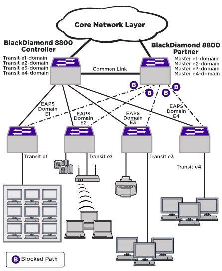
In this example, we have a common link with overlapping domains (and protected VLANs), which includes an EAPS controller and partner configuration. The result is a partial-mesh network design of EAPS from the access edge to the aggregation layer (see L2 Aggregation Network Layer).
The aggregation switches are configured to act as multi-function EAPS nodes to provide L2 connectivity services. After EAPS and L2 connectivity is configured, additional L3 routing configuration can be added.
Using redundant aggregation switches helps protect against a single point of failure at the switch level, while EAPS domains provide fault isolation and minimize the impact that failures have on the network. With shared port configurations, the partial-mesh physical design is maintained without broadcast loops, regardless of where a failure might occur.
To configure the L2 aggregate switches, complete the tasks described in the following sections on all aggregate switches: