Protected VPLS Access enables redundant nodes at the entry to a VPLS or H-VPLS network.
This feature provides fault tolerant connectivity from the customer VLAN to the backbone VPLS. This could be implemented by running Layer 2 protocols across the VPLS to block switch ports, but this can lead to sub optimal spanning tree topologies across the VPLS backbone and relatively long outages while the STP converges. Instead, the ExtremeXOS software has been enhanced to provide the ability to configure redundant VPLS switches using a dual-homed design that provides fast failover for protected access points.
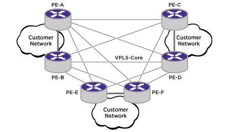
The first figure below shows fault-tolerant access in a full mesh core VPLS network while the second figure shows fault-tolerant access in a hierarchical VPLS network.
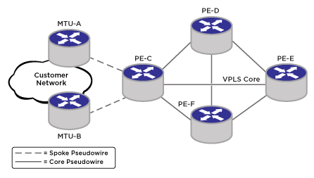
In the above figure, fault tolerance is provided at the customer site by MTU-A and MTU-B. A failure of either MTU-A or MTU-B does not result in any loss of customer connectivity beyond the failover time from one MTU to the other.
ESRP is employed to ensure that only one VPLS switch is active at any instant in time for a protected customer access point. Only the ESRP master switch forwards packets between the access network and the backbone VPLS network. This active primary switch retains this status based on a set of predefined tracking criteria. If the configured criteria can be better satisfied by the inactive secondary VPLS switch, the primary VPLS switch relinquishes control and the secondary switch assumes the active role. The secondary switch can also autonomously assume the active role if it detects that the primary switch has failed. This use of ESRP helps to prevent duplicate packet delivery and to prevent broadcast loops when the customer network is a loop topology.