The ESRP™, like the Virtual Router Redundancy Protocol (VRRP), allows multiple switches to provide redundant routing services to users.
ESRP is used to eliminate the single point of failure associated with manually configuring a default gateway address on each host in a network. Without using ESRP, if the configured default gateway fails, you must reconfigure each host on the network to use a different router as the default gateway. ESRP provides a redundant path for the hosts. Using ESRP, if the default gateway fails, the backup router assumes forwarding responsibilities.

Note
Support for ESRP operation over IPv6 networks was added in ExtremeXOS release 12.6.In addition to providing Layer 3 routing redundancy for IP and IPX, ESRP also provides Layer 2 redundancy features for fast failure recovery and to provide for dual-homed system design. In some instances, depending on network system design, ESRP can provide better resiliency than using Spanning Tree Protocol (STP) or Virtual Router Redundancy Protocol (VRRP). You can use Layer 3 and Layer 2 redundancy features in combination or independently. ESRP is available only on Extreme Networks switches. An example ESRP topology is shown in Example of a Basic ESRP Topology.
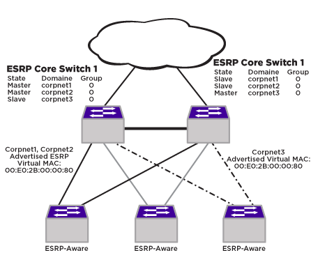
In this example, ESRP Core Switch #1 and ESRP Core Switch #2 are both configured with three ESRP domains. Each domain represents a separate ESRP instance and supports a unique set of VLANs. Each domain is configured to use one master VLAN and can support additional member VLANs. The switches exchange keep-alive packets for each VLAN independently.
Unless groups are configured, each ESRP domain supports two routers, one operating in the master state, and one operating in the slave state. Within an ESRP domain, any ESRP router can become the master, but only one ESRP router can be master at a time. Only the master can actively provide Layer 3 routing and/or Layer 2 switching for each VLAN. The master handles the forwarding, ARP requests, NDP messages, and routing for a particular VLAN. The slave router stands by, ready to take over if the master is no longer available.
Each switch in an ESRP topology has its own unique IP address (or IPX NetID) and a MAC address, which are required for basic IP connectivity. For each ESRP domain, there is a shared virtual IP address or IPX NetID and a MAC address, which are used for network client communications. The virtual IP address or IPX NetID is configured on all ESRP routers in a domain, and it is configured as the default gateway address on network clients in that domain. If the master ESRP router becomes unavailable, the backup ESRP router takes over using the same virtual IP address or IPX NetID.
The topology in Example of a Basic ESRP Topology shows that one switch serves as the master for the Corpnet1 and Corpnet2 domains, and the other switch serves as master for the Corpnet3 domain. This topology demonstrates the load sharing capability of ESRP. If one switch served as master for all ESRP domains, all traffic would be routed through that master, and the slave switch would be idle. Dividing the ESRP domain mastership between routers allows domain clients access to more bandwidth and reduces the likelihood of exceeding the capacity of a single master router.
You can use ESRP to achieve edge-level or aggregation-level redundancy.
Deploying ESRP in this area of the network allows you to simplify your network design, which is important in designing a stable network. ESRP also works well in meshed networks where Layer 2 loop protection and Layer 3 redundancy are simultaneously required.
Note
For complete information about platform support for ESRP, see the Switch Engine 32.2 Feature License Requirements document.