The MLAG feature allows you to combine ports on two switches to form a single logical connection to another network device. The other network device can be either a server or a switch that is separately configured with a regular LAG (or appropriate server port teaming) to form the port aggregation.
The following diagram displays the elements in a basic MLAG configuration:
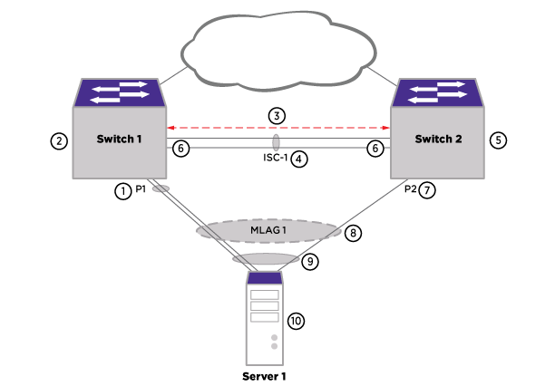
The operation of this feature requires two ExtremeXOS switches interconnected by an Inter-Switch connection (ISC). The ISC is a normal, directly connected, Ethernet connection and it is recommended that you engineer reliability, redundancy where applicable, and higher bandwidth for the ISC connection. Logically aggregate ports on each of the two switches by assigning MLAG identifiers (MLAG-ID). Ports with the same MLAG-ID are combined to form a single logical network connection. Each MLAG can be comprised of a single link or a LAG on each switch. When an MLAG port is a LAG, the MLAG port state remains up until all ports in the LAG go down.
As long as at least one port in the LAG remains active, the MLAG port state remains active. When an MLAG port (a single port or all ports in a LAG) fails, any associated MAC FDB entries are moved to the ISC, forcing traffic destined to the MLAG to be handled by the MLAG peer switch. Additionally, the MLAG peer switch is notified of the failure and changes its ISC blocking filter to allow transmission to the MLAG peer port. In order to reduce failure convergence time, you can configure MLAG to use ACLs for redirecting traffic via the "fast" convergence-control option.
Each of the two switches maintains the MLAG state for each of the MLAG ports and communicates with each other to learn the MLAG states, MAC FDB entries, and IP multicast entries of the peer MLAG switch.