Manual Configuration Example

The following example shows how to manually set up a controlling bridge (CB) with three attached bridge port extenders (BPEs) in a two-tier structure (see CB with Two-Tier BPEs Topology).
Click to expand in new window
CB with Two-Tier BPEs Topology
  1. Attach BPEs.
  2. On the CB, enable VPEX mode:
    5520.1 # enable vpex
    5520.1 # reboot
    Are you sure you want to reboot the switch? (y/N) Yes
    Slot-1 VPEX 5520.1 #
    Note

    Note

    After reboot, command prompt changes to show that you are in VPEX mode.
  3. Create LAGs between CB and first-tier BPEs:
    Slot-1 VPEX 5520.1 # enable sharing 1:10 group 1:10-1:11 lacp
    Slot-1 VPEX 5520.2 # enable sharing 1:20 group 1:20-1:21 lacp
  4. Configure slot identifiers associated with the first-tier BPEs:
    Slot-1 VPEX 5520.1 # configure vpex port 1:10 slot 110
    WARNING: This command will remove VLAN membership from the
             port 1:10.
             Do you want to continue? (y/N)Yes
    
    Slot-1 VPEX 5520.2 # configure vpex port 1:20 slot 120
    WARNING: This command will remove VLAN membership from the
             port 1:20.
             Do you want to continue? (y/N)Yes
    
    Slot-1 VPEX 5520.3 # show slot
    Slots    Type                 Configured           State       Ports   Flags
    --------------------------------------------------------------------------------
    Slot-1   5520        5520        Operational   64    M
    Slot-110 V400-48p-10GE4                            Operational   52
    Slot-120 V400-48p-10GE4                            Operational   52
    Flags : M - Backplane link to Master is Active
            B - Backplane link to Backup is also Active
            D - Slot Disabled
            I - Insufficient Power (refer to "show power budget")
    
    Slot-1 VPEX 5520.9 # show vpex
    Virtual Port Extender: Enabled
    Cascade
    Port     Slot
    =============
    1:10     110
    1:20     120
    Note

    Note

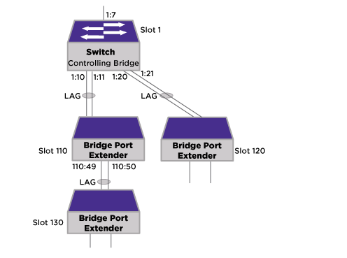
    Observe that the show slot command shows the CB as slot 1 with the two BPEs as slots 110 and 120.
    Note

    Note

    Observe that the show vpex command shows that ports 1:10 and 1:20 are the cascade ports connecting to the BPEs.
  5. Create LAG between first-tier and second-tier BPEs:
    Slot-1 VPEX 5520.1 # enable sharing 110:49 group 110:49, 110:50 lacp
  6. Configure slot identifier associated with the second-tier BPE:
    Slot-1 VPEX 5520.1 # configure vpex port 110:49 slot 130
    WARNING: This command will remove VLAN membership from the
             port 110:49.
             Do you want to continue? (y/N)Yes
    
    Slot-1 VPEX 5520.3 # show slot
    Slots    Type                 Configured           State       Ports   Flags
    --------------------------------------------------------------------------------
    Slot-1   5520        5520         Operational   64    M
    Slot-110 V400-48p-10GE4                            Operational   52
    Slot-120 V400-48p-10GE4                            Operational   52
    Slot-130 V400-48p-10GE4                            Operational   52
    Flags : M - Backplane link to Master is Active
            B - Backplane link to Backup is also Active
            D - Slot Disabled
            I - Insufficient Power (refer to "show power budget")
    
    Slot-1 VPEX 5520.9 # show vpex
    Virtual Port Extender: Enabled
    Cascade
    Port     Slot
    =============
    1:10     110
    1:20     120
    110:49   130
  7. Apply Layer 2 configuration:
    Slot-1 VPEX 5520.1 # configure vlan Default delete port all
    Slot-1 VPEX 5520.2 # create vlan v100 tag 100
    Slot-1 VPEX 5520.3 # configure vlan v100 add port 130:1-2, 120:1-2, 1:7 tagged
  8. If required, you can use standard show commands to troubleshoot the network from the CB using the counters:
Slot-1 VPEX 5520.3 # show port 130:49-50, 120:49-50, 1:7 statistics no-refresh
Port   Link  Tx Pkt    Tx Byte    Rx Pkt    Rx Byte  Rx Pkt Rx Pkt  Tx Pkt Tx Pkt
       State  Count      Count     Count      Count   Bcast  Mcast   Bcast  Mcast
====== ===== ======= ========== ========= ========== ======= ====== ======= ======
130:1  A   97045942 6209457963         0          0       0      0       0     35
130:2  R          0          0         0          0       0      0       0      0
120:1  A         36       4715  97001731 6206623104       0      0       0     35
120:2  A   95802538 6897726741  95784987 7279063658       0    512       0    697
1:7     A   97045942       4715  97001731 6206623104       0      0       0      0
====== ===== ======== ========= ========= ========== ====== ====== ======= ======
          > in Port indicates Port Display Name truncated past 8 characters
          > in Count indicates value exceeds column width. Use 'wide' option or '0' to clear.
          Link State: A-Active, R-Ready, NP-Port Not Present, L-Loopback

Slot-1 VPEX 5520.13 # show port 130:49-50, 120:49-50, 1:7 qosmonitor no-refresh
Port Qos Monitor
Port          QP1       QP2       QP3       QP4       QP5       QP6       QP7       QP8
              Pkt       Pkt       Pkt       Pkt       Pkt       Pkt       Pkt       Pkt
             Xmts      Xmts      Xmts      Xmts      Xmts      Xmts      Xmts      Xmts
========================================================================================
130:49   119682459         0         0         0         0         0         0        45
130:50           0         0         0         0         0         0         0         0
120:49           0         0         0         0         0         0         0        45
120:50   119803233         0         0         0         0         0         0       923
1:7      119803233         0         0         0         0         0         0       923