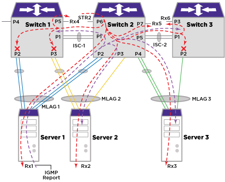
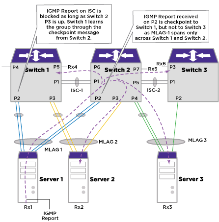
The receiver Rx1 sends an IGMP report towards Server 1. Since server 1 is connected to both Switch 1 and Switch 2 through a LAG, let us assume that it selects a port towards Switch 2 to forward the report. This results in Switch 2 receiving a report on port P2. It adds the port to the group table. Switch 2 sends a checkpoint message to Switch 1 since Switch 1 is the MLAG peer for MLAG-1. But Switch 2 doesn‘t checkpoint the report to Switch 3 since Switch 3 is not an MLAG peer for MLAG-1. However, Switch 2 forwards the report towards Switch 3 over ISC. Switch 3 would learn this on ISC port. The group information tables on each of the switches appears below.
| Group | Port |
|---|---|
| G1 | P2 |
| Group | Port |
|---|---|
| G1 | P2 |
| Group | Port |
|---|---|
| G1 | P1 |
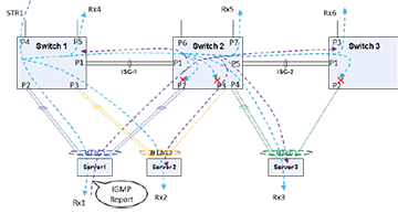
Multicast Stream Ingressing Example depicts a scenario where a multicast stream STR1 ingressing Switch 1 will reach Rx1 and Rx2 directly via P2 and P3 respectively. Similarly traffic ingressing Switch 2 will reach Rx3 through P4 directly.
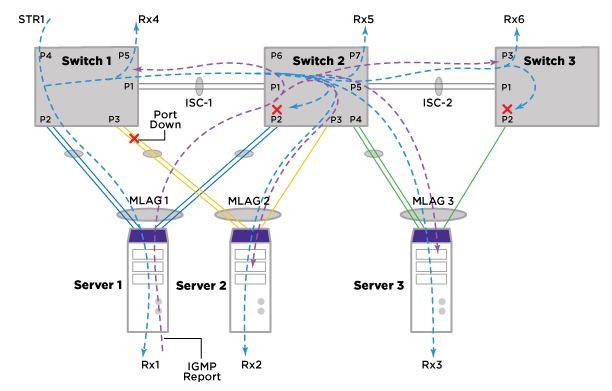
Traffic Flow with Local MLAG Port Down figure depicts a traffic flow scenario when the local MLAG port is down. When the local MLAG port is down, IGMP group information received from the peer MLAG router will result in ISC being added as egress port. Now traffic stream STR1 ingressing Switch 1 will go over ISC-1 to Switch 2 where it gets forwarded towards Server 2 over P3.
Multicast Stream Ingressing Switch 2 Example illustrates a scenario where a multicast stream STR2 ingressing Switch 2 will reach Rx1, Rx2 and Rx3 directly via P2, P3 and P4 respectively.