This section introduces the basic concepts of BGP/MPLS VPNs as described in the Internet RFC 4364. BGP/MPLS VPN Example illustrates an example BGP/MPLS VPN network configuration that includes two VPNs: VPN-A comprises three sites, and VPN-B comprises two. Both VPNs use the same set of IP addresses as defined in RFC 1918.
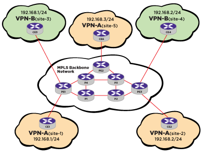
The Customer Edge boxes represent switches or routers, while the Provider Edge and P(rovider) boxes are routers. If the CE box is a router, then it only needs to peer with the adjacent PE router(s). The PE and P routers form the core MPLS network. The P routers only maintain routing information for the core MPLS network, while the PE routers only maintain routing information for the VPNs they support. This ensures that no single router maintains routing information for all the VPNs.
Since a PE router can support multiple VPNs that may have overlapping address spaces, each PE router must maintain multiple Virtual Routing and Forwarding tables (VRFs). In the example, each site is a member of one VPN, and the PE router is configured to associate a particular VPN with each physical interface to a CE router. The PE router maintains one VRF for each VPN, and packets received from a particular physical interface are forwarded using the VRF for the VPN associated with that interface.
VRFs for a specific VPN are populated in two ways: (1) when the PE router learns routes from a directly-attached CE router that is a member of the VPN, and (2) when the PE router receives routes for the VPN through MBGP from another PE router. The PE router can learn the routes that are reachable at a particular CE router‘s site through configuration (static routes), or by routing protocol exchanges with the CE router.
VPN route distribution uses BGP-4 Multiprotocol Extensions that enable BGP to carry routes from multiple address families. The VPN-IPv4 address family supports BGP/MPLS VPNs. A VPN-IPv4 address is a 12-byte entity, beginning with an 8-byte (RD) and ending with a 4-byte IPv4 address. The RD makes it possible to create distinct routes to a common IPv4 address prefix, which is necessary when the same IPv4 address prefix is used in two different VPNs.
The purpose of the RD is solely to allow one to create distinct routes to a common IPv4 address prefix. The Route target attribute is used to identify a set of VRFs. Every VRF is associated with one or more route targets. Export route targets identify the set of route targets that a PE router attaches to a route learned from a particular CE site. Import route targets identify the set of route targets that determine whether a route received from another PE router can be inserted in a particular VRF. A VPN-IPv4 route can only be installed in a particular VRF if there is a route target that is both one of the route‘s targets, and one of the VRF‘s import route targets. Route targets allow a PE router to only maintain routing information for the VPNs it is supporting. Using import and export route targets offers flexibility in constructing a variety of VPN topologies (such as a fully-meshed closed user group, or a hub-and-spoke architecture). Route Targets are encoded as BGP Extended Communities attributes.
When distributing a VPN route through BGP, a PE router includes its own IP address as the BGP next hop (next-hop-self). The PE router always assigns and distributes an MPLS label for each customer VPN VRF that it receives from directly connected sites (CEs). BGP-distributed MPLS labels require that there be a label switched path between the PE router that installs the BGP-distributed route and the PE router that is the BGP next hop of that route. This is necessary because a multi-label stack is used to forward VPN packets across the MPLS backbone.
The outer MPLS label gets the packet across the backbone. This label is obtained from the MPLS signaling protocols, and is associated with the best LSP to the BGP next hop address of the PE Router that advertised the VPN route. The inner MPLS label is obtained from BGP, and is associated with the best route to the VPN destination address. This label identifies the VRF that the egress PE Router uses to forward the packet to a CE device, and may indicate the outgoing interface that the packet should be forwarded over (along with the appropriate link layer header for that interface).
The use of a two-level MPLS label stack is an important scalability attribute of the model, because it is the two-level label stack that enables the P routers to operate without containing routes for any of the VPNs.
One of the core principles of operating a VPN is maintaining separation between the customer networks. L3VPN uses a special format to represent customer routes within the provider‘s network. This format allows each provider router to uniquely view routes from different customers as separate, even when they advertise the same IPv4 prefix. The format consists of these fields: Mask, MPLS label, route distinguisher, and IPv4 prefix.
The following list identifies the limitations of the L3VPN feature: