5520.1 # enable vpex
5520.1 # reboot
Are you sure you want to reboot the switch? (y/N) Yes
Slot-1 VPEX 5520.1 #

Note
After reboot, command prompt changes to show that you are in VPEX mode.Slot-1 VPEX 5520.1 # configure vpex port 1:10 slot 110
WARNING: This command will remove VLAN membership from the
port 1:10.
Do you want to continue? (y/N)Yes
Slot-1 VPEX 5520.2 # configure vpex port 1:20 slot 120
WARNING: This command will remove VLAN membership from the
port 1:20.
Do you want to continue? (y/N)Yes
Slot-1 VPEX 5520.3 # show slot
Slots Type Configured State Ports Flags
--------------------------------------------------------------------------------
Slot-1 5520 5520 Operational 64 M
Slot-110 V400-48p-10GE4 Operational 52
Slot-120 V400-48p-10GE4 Operational 52
Flags : M - Backplane link to Master is Active
B - Backplane link to Backup is also Active
D - Slot Disabled
I - Insufficient Power (refer to "show power budget")
Slot-1 VPEX 5520.9 # show vpex
Virtual Port Extender: Enabled
Cascade
Port Slot
=============
1:10 110
1:20 120
Note
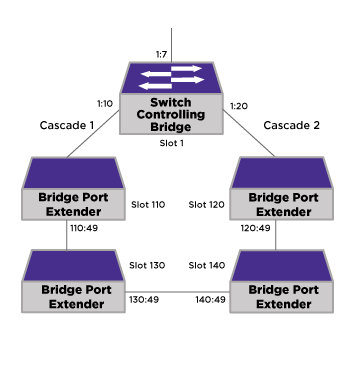
Observe that the show slot command shows the CB as slot 1 with the two BPEs as slots 110 and 120.Note
Observe that the show vpex command shows that ports 1:10 and 1:20 are the cascade ports connecting to the BPEs.Slot-1 VPEX 5520.1 # configure vpex port 110:49 slot 130
WARNING: This command will remove VLAN membership from the
port 110:49.
Do you want to continue? (y/N)Yes
Slot-1 VPEX 5520.2 # configure vpex port 120:49 slot 140
WARNING: This command will remove VLAN membership from the
port 120:49.
Do you want to continue? (y/N)Yes
Slot-1 VPEX 5520.3 # show slot
Slots Type Configured State Ports Flags
--------------------------------------------------------------------------------
Slot-1 5520 5520 Operational 64 M
Slot-110 V400-48p-10GE4 Operational 52
Slot-120 V400-48p-10GE4 Operational 52
Slot-130 V400-48p-10GE4 Operational 52
Slot-140 V400-48p-10GE4 Operational 52
Flags : M - Backplane link to Master is Active
B - Backplane link to Backup is also Active
D - Slot Disabled
I - Insufficient Power (refer to "show power budget")
Slot-1 VPEX 5520.9 # show vpex
Virtual Port Extender: Enabled
Cascade
Port Slot
=============
1:10 110
1:20 120
110:49 130
120:49 140
Note
Observe that the show slot command shows the CB as slot 1 with the four BPEs as slots 110, 120, 130, and 140.Note
Observe that the show vpex command shows that ports 1:10, 1:20, 110:49, and 120:49 are the cascade ports connecting to the BPEs.