The following diagrams illustrate the components on the front panels of the VSP 4450 Series switches. Ethernet ports 1-50 on the switch are considered to be in slot 1.
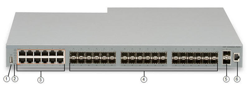
USB port.
Switch LEDs for system power (PWR), switch status (Status), and redundant power supply (RPS).
12 10/100/1000 Mbps RJ-45 ports with PoE+. LEDs indicating port activity are above the ports.
36 100/1000 Mbps SFP ports.
Two 1/10G SFP+ ports.
Console Port.
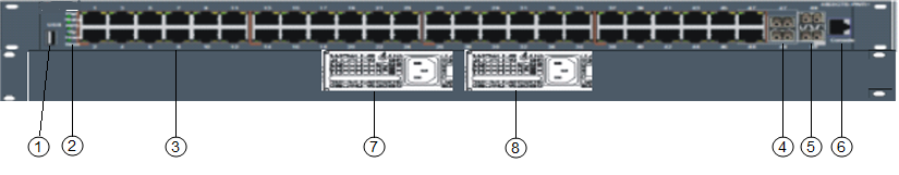
USB port but without a USB or a USB device cover.

Note
The VSP 4450GTX-HT-PWR+ model does not require a USB device in the USB port for normal operation. The USB port can be used for additional storage using a USB memory stick.
Switch LEDs for system power (PWR), switch status (Status), and redundant power supply (RPS).
48 10/100/1000 Mbps RJ-45 ports with 802.3at PoE+. LEDs indicating port activity are above the ports.
Two combo port SFP slots. Supports 1G SFPs and 100Base low speed SFPs.
Two SFP+ slots. Supports 1G SFPs and 10G SFP+s.
Console Port.
Field-replaceable 1000W AC power supply unit (PSU).
Second field-replaceable AC power supply unit for redundancy or additional PoE.
USB port.
Switch LEDs for system power (PWR), switch status (Status), and redundant power supply (RPS).
12 10/100/1000 Mbps RJ-45 ports. LEDs indicating port activity are above the ports.
36 100/1000 Mbps SPF ports.
Two SFP+ slots. Supports 1G SFPs and 10G SFP+s.
Console Port.