The following section describes a simple configuration example to configure Distributed Virtual Routing (DvR) over a Fabric Connect (SPB) network.
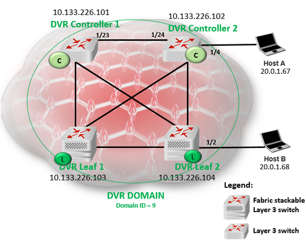
In this example, you configure two DvR Controllers (with IP addresses 10.133.226.101 and 10.133.226.102) and two DvR Leaf nodes (with IP addresses 10.133.226.103 and 10.133.226.104), in a single DvR domain with domain ID 9. Hosts connect to the DvR nodes as shown in the figure.
On the switches to be configured as DvR Controllers:
Ensure that you configure Fabric Connect.
Ensure that you configure IP Shortcuts on the node. This is necessary for proper functioning of the node as a DvR Controller.
Verify that the dvr-leaf-mode boot flag is disabled on the node. To verify the setting, enter show boot config flags in Privileged EXEC mode.
On the switches to be configured as DvR Leaf nodes:
Ensure that you configure Fabric Connect.
DvR Controller configuration — Controller 1 and Controller 2:
The following examples show verification on one of the switches. Perform this verification on both switches.
Switch1:1>en
Switch1:1#show spbm
                                  spbm : enable
                             ethertype : 0x8100
                      nick-name server : enable
                  nick-name allocation : static
                nick-name server range : B.00.00-B.FF.FF
Switch1:1#show isis spbm

===========================================================================================
                                 ISIS SPBM Info
===========================================================================================
SPBM       B-VID      PRIMARY    NICK     LSDB     IP       IPV6     MULTICAST  SPB-PIM-GW
INSTANCE              VLAN       NAME     TRAP
-------------------------------------------------------------------------------------------
1          4051-4052  4051       0.10.01  disable  enable   disable  enable     disable

===========================================================================================
                              ISIS SPBM SMLT Info
===========================================================================================
SPBM       SMLT-SPLIT-BEB       SMLT-VIRTUAL-BMAC     SMLT-PEER-SYSTEM-ID
INSTANCE
-------------------------------------------------------------------------------------------
1          primary              00:00:00:00:00:00


--------------------------------------------------------------------------------
 Total Num of SPBM instances: 1
--------------------------------------------------------------------------------
Switch1:1#show isis

==============================================================================
                               ISIS General Info
==============================================================================
                            AdminState : enabled
                            RouterType : Level 1
                             System ID : 00bb.0000.0101
                  Max LSP Gen Interval : 900
                                Metric : wide
                   Overload-on-startup : 20
                              Overload : false
                         Csnp Interval : 10
                         PSNP Interval : 2
                     Rxmt LSP Interval : 5
                             spf-delay : 100
                           Router Name : Cont-1
                     ip source-address : 10.0.0.101
                   ipv6 source-address :
              ip tunnel source-address :
                            Tunnel vrf :
                         ip tunnel mtu :
                     Num of Interfaces : 4
                 Num of Area Addresses : 1
                   Inband Mgmt Clip IP :
                              backbone : disabled
              Dynamically Learned Area : 00.0000.0000
                            FAN Member : No
                  Multi-Area OperState : disabled
                         Hello Padding : enabled
Switch:1>en
Switch:1#conf t
Enter configuration commands, one per line.  End with CNTL/Z.
Switch:1(config)#dvr controller 9
Switch:1(config)#show dvr

==================================================================
                    DVR Summary Info
==================================================================
Domain ID                      : 9
Domain ISID                    : 16678219
Backbone ISID                  :
Role                           : Controller
My SYS ID                      : 00:bb:00:00:81:21
Operational State              : Up
GW MAC                         : 00:00:5e:00:01:25
InjectDefaultRouteDisable(GRT) : Disabled
Switch:1>en
Switch:1#conf t
Enter configuration commands, one per line.  End with CNTL/Z.
Switch:1(config)#dvr controller 9
Switch:1(config)#show dvr

==================================================================
                    DVR Summary Info
==================================================================
Domain ID                      : 9
Domain ISID                    : 16678219
Backbone ISID                  : 16678216
Role                           : Controller
My SYS ID                      : 00:bb:00:00:81:21
Operational State              : Up
GW MAC                         : 00:00:5e:00:01:25
InjectDefaultRouteDisable(GRT) : Disabled
Switch1:1#show dvr members

============================================================================================
                                          DVR Members (Domain ID: 2)
============================================================================================
System Name                              Nick-Name        Nodal MAC              Role
--------------------------------------------------------------------------------------------
Cont-1                                   0.10.01          00:bb:00:00:01:01      Controller
Cont-2                                   0.10.02          00:bb:00:00:01:02      Controller

2 out of 2 Total Num of DVR Members displayed
--------------------------------------------------------------------------------------------
Layer 2 VSN (VLAN) configuration on the DvR Controllers:
Switch1:1(config)#vlan create 200 type port-mstprstp 0
Switch1:1(config)#vlan i-sid 200 20200
Switch1:1(config)#interface vlan 200
Switch1:1(config)#dvr gw-ipv4 20.0.1.1
Switch1:1(config)#dvr enable
Switch1:1(config)#ip address 20.0.1.2 255.255.0.0
Switch1:1(config)#vlan create 202 type port-mstprstp 0
Switch1:1(config)#vlan i-sid 202 20202
Switch1:1(config)#interface vlan 202
Switch1:1(config)#dvr gw-ipv4 20.2.1.1
Switch1:1(config)#dvr enable
Switch1:1(config)#ip address 20.2.1.2 255.255.0.0
Switch1:1(config)#exit
Switch1:1#
Switch2:1(config)#vlan create 200 type port-mstprstp 0
Switch2:1(config)#vlan i-sid 200 20200
Switch2:1(config)#interface vlan 200
Switch2:1(config)#dvr gw-ipv4 20.0.1.1
Switch2:1(config)#dvr enable
Switch2:1(config)#ip address 20.0.1.3 255.255.0.0
Switch2:1(config)#vlan create 202 type port-mstprstp 0
Switch2:1(config)#vlan i-sid 202 20202
Switch2:1(config)#interface vlan 202
Switch2:1(config)#dvr gw-ipv4 20.2.1.1
Switch2:1(config)#dvr enable
Switch2:1(config)#ip address 20.2.1.3 255.255.0.0
Switch2:1(config)#exit
Switch2:1#
View the DvR interfaces.
On Controllers, DvR interfaces are created when you configure IP on a DvR enabled Layer 2 VSN (VLAN, I-SID). You can also view the administrative state of these interfaces on the Controller.
Switch1:1#show dvr interfaces

========================================================================================================================
                                                     DVR Interfaces
========================================================================================================================
                                                                                        Admin        SPBMC      IGMP
Interface       Mask           L3ISID     VRFID    L2ISID     VLAN     GW IPv4          State        State      Version
------------------------------------------------------------------------------------------------------------------------
20.0.1.2        255.255.0.0    0          0        20200      200      20.0.1.1         enable       disable    2
20.2.1.2        255.255.0.0    0          0        20202      202      20.2.1.1         enable       disable    2

2 out of 2 Total Num of DVR Interfaces displayed
------------------------------------------------------------------------------------------------------------------------
View the DvR host entries learned locally on the S-UNI port.
Switch1:1#show dvr host-entries

=======================================================================================================
                                                         DVR Host-Entries
=======================================================================================================
                 HOST                L3VSN      L2VSN                   DOMAIN
IP-ADDRESS       MAC-ADDRESS         ISID       ISID       PORT         ID     TYPE         NEXT HOP
-------------------------------------------------------------------------------------------------------
20.0.1.2         b0:ad:aa:42:ed:04   0          20200      cpp          9      LOCAL        Cont-1
20.2.1.2         b0:ad:aa:42:ed:04   0          20202      cpp          9      LOCAL        Cont-1
2 out of 2 Total Num of DVR Host Entries displayed
--------------------------------------------------------------------------------------------------------
View the DvR database. All IP subnet routes configured on the Controller, for the DvR domain, are displayed.
Switch1:1#show dvr database
===============================================================================================================================
                                                           DVR DATABASE
===============================================================================================================================
                                NEXT                       L3VSN     L2VSN     OUTGOING             SPB  PREFIX
DEST            MASK            HOP                        ISID      ISID      INTERFACE            COST COST   AGE
-------------------------------------------------------------------------------------------------------------------------------
20.0.1.2        255.255.255.255 Cont-1                     0         20200     cpp                  10   1      1 day(s), 06:41:40
20.2.1.2        255.255.255.255 Cont-1                     0         20202     cpp                  10   1      1 day(s), 06:41:40

2 out of 2 Total Num of DVR Database entries displayed
-------------------------------------------------------------------------------------------------------------------------------
View the DvR routes for the subnets 20.0.0.0 and 20.2.0.0.
Switch1:1#show dvr routes

=====================================================================================================
                                                            DVR Routes
=====================================================================================================
                                     NEXT               L3VSN         L2VSN
DEST            MASK                 HOP                ISID          ISID        TYPE      COST
------------------------------------------------------------------------------------------------------
20.0.0.0        255.255.0.0          Cont-1             0             20200       -         1
20.2.0.0        255.255.0.0          Cont-1             0             20202       -         1

2 out of 2 Total Num of DVR Routes displayed
-------------------------------------------------------------------------------------------------------
TYPE Legend: E=Ecmp Route
Layer 3 configuration on the DvR Controllers
Switch1:1(config)#ip vrf vrf501 vrfid 501
Switch1:1(config)#vlan create 501 type port-mstprstp 0
Switch1:1(config)#vlan i-sid 501 50501
Switch1:1(config)#interface Vlan 501
Switch1:1(config)#vrf vrf501
Switch1:1(config)#dvr gw-ipv4 50.1.1.1
Switch1:1(config)#dvr enable
Switch1:1(config)#ip address 50.1.1.2 255.255.0.0
Switch1:1(config)#router vrf vrf501
Switch1:1(router-vrf)#i-sid 55501
Switch1:1(router-vrf)#ipvpn enable
Switch1:1(router-vrf)#exit
Switch1:1(config)#
Switch2:1(config)#ip vrf vrf501 vrfid 501
Switch2:1(config)#vlan create 501 type port-mstprstp 0
Switch2:1(config)#vlan i-sid 501 50501
Switch2:1(config)#interface Vlan 501
Switch2:1(config)#vrf vrf501
Switch2:1(config)#dvr gw-ipv4 50.1.1.1
Switch2:1(config)#dvr enable
Switch2:1(config)#ip address 50.1.1.3 255.255.0.0
Switch2:1(config)#router vrf vrf501
Switch2:1(router-vrf)#i-sid 55501
Switch2:1(router-vrf)#ipvpn enable
Switch2:1(router-vrf)#exit
Switch2:1(config)#
View the DvR host entries.
Switch2:1(config)#show dvr host-entries l3isid 55501

=======================================================================================================
                                                         DVR Host-Entries
=======================================================================================================
                 HOST                L3VSN      L2VSN                  DOMAIN
IP-ADDRESS       MAC-ADDRESS         ISID       ISID       PORT        ID     TYPE         NEXT HOP
-------------------------------------------------------------------------------------------------------
50.1.1.2         b0:ad:aa:42:ed:08   55501      50501      cpp         9      LOCAL        Cont-1
50.1.1.3         b0:ad:aa:4c:3d:02   55501      50501      1/23        9      DYNAMIC      Cont-2

2 out of 3267 Total Num of DVR Host Entries displayed
-------------------------------------------------------------------------------------------------------
View the DvR interfaces.
Switch2:1(config)#show dvr interfaces l3isid 55501

========================================================================================================================
                                                     DVR Interfaces
========================================================================================================================
                                                                                        Admin        SPBMC      IGMP
Interface       Mask           L3ISID     VRFID    L2ISID     VLAN     GW IPv4          State        State      Version
------------------------------------------------------------------------------------------------------------------------
50.1.1.2        255.255.0.0    55501      501      50501      501      50.1.1.1         enable       disable    2

1 out of 291 Total Num of DVR Interfaces displayed
Switch2:1(config)#show dvr database l3isid 55501

=====================================================================================================================
                                                           DVR DATABASE
=====================================================================================================================
                                NEXT          L3VSN     L2VSN     OUTGOING             SPB  PREFIX
DEST            MASK            HOP           ISID      ISID      INTERFACE            COST COST   AGE
---------------------------------------------------------------------------------------------------------------------
50.1.0.0        255.255.0.0     Cont-1        55501     50501     cpp                  10   1      0 day(s), 01:26:49
50.1.1.2        255.255.255.255 Cont-1        55501     50501     cpp                  10   1      0 day(s), 01:26:49
50.1.1.3        255.255.255.255 Cont-2        55501     50501     1/23                 10   1      0 day(s), 01:24:53

3 out of 3558 Total Num of DVR Database entries displayed
----------------------------------------------------------------------------------------------------------------------
DvR Leaf configuration — Leaf 1 and Leaf 2

Caution
Ensure that you save the current configuration on the switch, before you enable the flag.
Enabling the flag removes all existing non-DvR configuration on the switch, such as platform VLANs and their IP address configuration, CLIP configuration, routing protocol configuration and VRF configuration. The gateway IPv4 address, if configured, is also removed.
On switch with IP address 10.133.226.104, configure the boot flag and reboot the switch.
Switch3:1>en
Switch3:1#conf t
Enter configuration commands, one per line.  End with CNTL/Z.
Switch3:1(config)#boot config flags dvr-leaf-mode
Switch3:1(config)#save config
Switch3:1(config)#reset
On switch with IP address 10.133.226.105, configure the boot flag and reboot the switch.
Switch4:1>en
Switch4:1#conf t
Enter configuration commands, one per line.  End with CNTL/Z.
Switch4:1(config)#boot config flags dvr-leaf-mode
Switch4:1(config)#save config
Switch4:1(config)#reset
Configure switch with IP address 10.133.226.104 as DvR Leaf 1; verify the configuration.
Switch3:1(config)#dvr Leaf 9
Switch3:1(config)#show dvr

=========================================================================
                                     DVR Summary Info
=========================================================================
Domain ID                      : 9
Domain ISID                    : 16678219
Role                           : Leaf
My SYS ID                      : 00:bb:00:00:80:05
Operational State              : Up
GW MAC                         : 00:00:5e:00:01:25
Inband Mgmt Clip IP            :
Virtual Ist local address      :
Virtual Ist local subnet mask  :
Virtual Ist peer address       :
Virtual Ist cluster-id         :
Virtual Ist ISID               :
Configure switch with IP address 10.133.226.105 as DvR Leaf 2; verify the configuration.
Switch4:1(config)#dvr Leaf 9
Switch4:1(config)#show dvr

=========================================================================
                                     DVR Summary Info
=========================================================================
Domain ID                      : 9
Domain ISID                    : 16678219
Role                           : Leaf
My SYS ID                      : 00:bb:00:00:80:05
Operational State              : Up
GW MAC                         : 00:00:5e:00:01:25
Inband Mgmt Clip IP            :
Virtual Ist local address      :
Virtual Ist local subnet mask  :
Virtual Ist peer address       :
Virtual Ist cluster-id         :
Virtual Ist ISID               :
On Leaf node 1 (IP address 10.133.226.105):
Switch3:1(config)#i-sid 20200 elan
Switch3:1(elan:20200)#c-vid 200 port 1/2
Switch3:1(config)#exit
View the host connections.
Switch3:1#show dvr host-entries nh-as-mac

==============================================================================================================
                                                         DVR Host-Entries
==============================================================================================================
                 HOST                L3VSN      L2VSN                  DOMAIN
IP-ADDRESS       MAC-ADDRESS         ISID       ISID       PORT        ID     TYPE         NEXT HOP
--------------------------------------------------------------------------------------------------------------
20.0.1.67        00:00:00:00:00:67   0          20200      1/4          9      DYNAMIC      00:bb:00:00:81:21
20.0.1.68        00:00:00:00:00:68   0          20200      1/2          9      DYNAMIC      00:bb:00:00:81:21
2 out of 2 Total Num of DVR Host Entries displayed
--------------------------------------------------------------------------------------------------------------
On Leaf node 2 (IP address 10.133.226.105):
Switch4:1(config)#i-sid 20200 elan
Switch4:1(elan:20200)#c-vid 200 port 1/2
Switch4:1(config)#exit
View the host connections.
Switch4:1#show dvr host-entries nh-as-mac

==============================================================================================================
                                                         DVR Host-Entries
==============================================================================================================
                 HOST                L3VSN      L2VSN                  DOMAIN
IP-ADDRESS       MAC-ADDRESS         ISID       ISID       PORT        ID     TYPE         NEXT HOP
--------------------------------------------------------------------------------------------------------------
20.0.1.67        00:00:00:00:00:67   0          20200      1/4          9      DYNAMIC      00:bb:00:00:81:21
20.0.1.68        00:00:00:00:00:68   0          20200      1/2          9      DYNAMIC      00:bb:00:00:81:21
2 out of 2 Total Num of DVR Host Entries displayed
--------------------------------------------------------------------------------------------------------------
Switch1:1#show dvr members

================================================================================================
                                          DVR Members (Domain ID: 2)
================================================================================================
System Name                              Nick-Name        Nodal MAC                 Role
------------------------------------------------------------------------------------------------
Cont-1                                   0.10.01          00:bb:00:00:01:01         Controller
Cont-2                                   0.10.02          00:bb:00:00:01:02         Controller
Leaf1                                    0.10.04          00:bb:00:00:80:04         Leaf
Leaf2                                    0.10.05          00:bb:00:00:80:05         Leaf

4 out of 4 Total Num of DVR Members displayed
-------------------------------------------------------------------------------------------------