The Authenticator facilitates the authentication exchanges that occur between the Supplicant and the Authentication Server. The Authenticator PORT ACCESS ENTITY (PAE) encapsulates the EAP message into a RADIUS packet, and then sends the packet to the Authentication Server.
The Authenticator manages the access to controlled port. At system initialization, or when a Supplicant initially connects to one of the controlled ports on the device, the system blocks data traffic of the Supplicant until gets authenticated. After the Authentication Server notifies the Authenticator PAE about the success or failure of the authentication, the Authenticator decides whether to permit/deny the traffic of client on controlled port.
non-EAPoL (NEAP) frames transmit according to the following rules:
If authentication succeeds, the client blocked from accessing is allowed to the controlled port, which means the system allows all the incoming and outgoing traffic from that client through the port.
If authentication fails, client is blocked from accessing, which means both incoming and outgoing traffic is not allowed to client.
The following figure illustrates how the switch, configured with EAP, reacts to a new network connection.
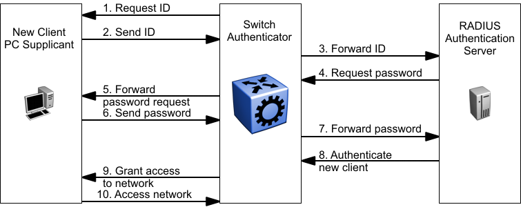
In the preceding figure, the switch uses the following steps to authenticate a new client:
The switch detects a new connection on one of its EAP-enabled ports and requests a user ID from the new client PC.
The new client sends its user ID to the switch.
The switch uses RADIUS to forward the user ID to the RADIUS server.
The RADIUS server responds with a request for the password of the user.
The switch forwards the request from the RADIUS server to the new client.
The new client sends an encrypted password to the switch, within the EAP packet.
The switch forwards the EAP packet to the RADIUS server.
The RADIUS server authenticates the password.
The switch grants the new client access to the network.
The new client accesses the network.
If the RADIUS server cannot authenticate the new client, it denies the new client access to the network.
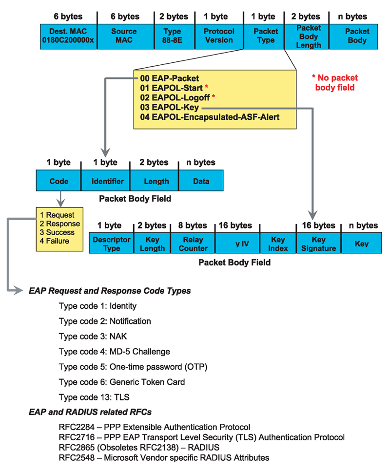
The following figure shows the Ethernet frames and the corresponding codes for EAP as specified by 802.1x.
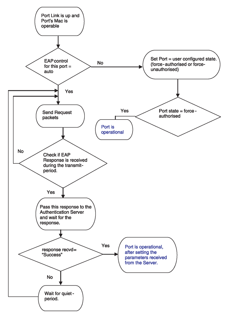
The following figure shows the flow diagram for EAP on a switch.