SPB-PIM Gateway Base Case Deployment Scenario
There are several different customer topology scenarios for the SPB-PIM Gateway (SPB-PIM GW) feature deployment . One of these scenarios, shown in Figure 5, is fully described here, along with configuration details, and display information.
SPB domain
PIM domain
RP
PIM-A1
PIM-A2
PIM-B
PIM-C
SPB-PIM Gateway Controller node
Two Gateway nodes, BEB-A1 and BEB-A2
BEB-A1 is connected to the PIM network through a SPB-PIM Gateway interface to the PIM router PIM-A1
BEB-A2 is connected to the PIM network through a SPB-PIM Gateway interface to the PIM router PIM-A2

Note
PIM-A1 and PIM-A2 routers attached to the BEBs SPB-PIM Gateway interface have standard PIM configured on their side of the interface.
The SPB cloud has a BEB-B to which the source S2 is connected
The SPB cloud has a BEB-C to which a receiver R1 is connected
Note
You can place the controller anywhere in the SPB cloud. The controller can be in the boundary or the core. Anywhere there is a connection into the PIM network from the SPB network, there must be a Gateway node(s) and Gateway interface(s).
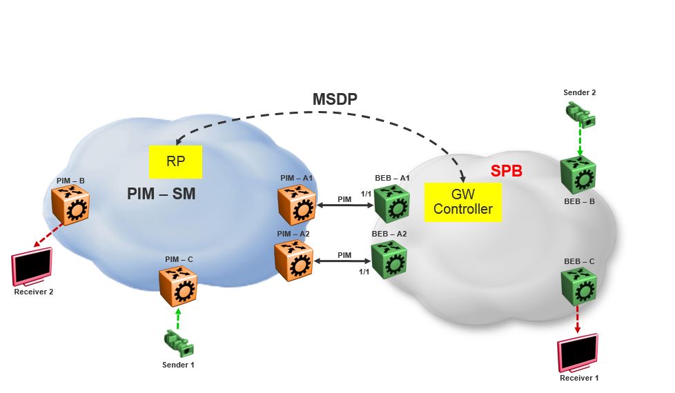
The SPB-PIM Gateway nodes BEB-A1 and BEB-A2 from the SPB cloud are connected to the PIM network. The connection is established by SPB-PIM Gateway interface connections to PIM routers PIM-A1 and PIM-A2. A MSDP connection is established between the RP from the PIM domain and the SPB-PIM Gateway Controller from the SPB domain. A MSDP connection is established to exchange the multicast source information between the RP and the SPB Controller. Unicast routing or reachability is setup before establishing the MSDP connection between the RP and the Gateway controller. The Unicast setup is not shown in the above figure.
SPB-PIM Gateway base case configuration example
Before you begin
The Shortest Path Bridging (SPB) infrastructure must be configured and setup in the SPB domain (not shown in this example)
Protocol Independent Multicast (PIM) infrastructure must be configured and setup in the PIM domain (not shown in this example)
Unicast routing table must be setup in the PIM domain to ensure reachability of the Multicast Source Discovery Protocol (MSDP) peer and source S2 from the SPB network
Unicast routing table must be setup in the SPB domain to ensure reachability of the MSDP peer and source S1 from the PIM network
Example
Node: Gateway controller
Configure ISIS and SPBM:
Switch:1#configure terminal
Switch:1(config)#spbm
Switch:1(config)#router isis
Switch:1(config-isis)#system-id 0026.0026.0026
Switch:1(config-isis)#manual-area 01.0202.0303.04
Switch:1(config-isis)#spbm 1
Switch:1(config-isis)#spbm 1 nick-name 0.00.26
Switch:1(config-isis)#spbm 1 b-vid 10,20 primary 10
Switch:1(config-isis)#vlan create 10 name bvlan1 type spbm-bvlan
Switch:1(config)#vlan create 20 name bvlan2 type spbm-bvlan
Switch:1(config)#router isis enable
Switch:1(config)#interface gigabitEthernet 1/1
Switch:1(config-if)#isis
Switch:1(config-if)#isis spbm 1
Switch:1(config-if)#isis enable
Switch:1(config-if)#no shutdown
-
Enable IPSC to setup Unicast route table. This setup ensures reachability of Rendezvous Point (RP) in the PIM network
-
Create a loopback interface 2.0.2.2 to enable IPSC and MSDP originator-id
-
Enable Multicast over Fabric Connect
-
Configure static route and direct route redistrubution
-
Apply the static route and direct route redistribution
Note
Static route is used to reach RP for the below sample configuration.
Switch:1(config)#interface loopback 1
Switch:1(config-if)#ip address 2.0.2.2/32
Switch:1(config)#router isis
Switch:1(config-isis)#ip-source-address 2.0.2.2
Switch:1(config-isis)#spbm 1 ip enable
Switch:1(config-isis)#spbm 1 multicast enable
Switch:1(config-isis)#
Switch:1(config-isis)#redistribute static
Switch:1(config-isis)#redistribute static enable
Switch:1(config-isis)#redistribute direct
Switch:1(config-isis)#redistribute direct enable
Switch:1(config-isis)#
Switch:1(config-isis)#end
Switch:1#isis apply redistribute static
Switch:1#isis apply redistribute direct
MSDP Configuration:
Create an instance for the MSDP session. This IP interface is used for establishing an MSDP session with an RP in the PIM network. The source IP address used for the MSDP session must not be the newly created IP interface. The originator-id specifically configured for MSDP is used as the source IP address to establish the MSDP session. The originator-id is also used by the RP in the source active (SA) messages sent to the MSDP peers. The CLIP configured earlier is used as the originator-id.
Switch:1#configure terminal
Switch:1(config)#vlan create 2100 type port-mstprstp 0
Switch:1(config)#vlan members add 2100 1/3 portmember
Switch:1(config)#interface vlan 2100
Switch:1(config-if)#ip address 21.0.0.1/24
Switch:1(config-if)#exit

Switch:1(config)#ip msdp originator-id 2.0.2.2
Switch:1(config)#ip msdp enable
Switch:1(config)#ip msdp peer 21.0.0.2
Switch:1(config)#ip msdp peer 21.0.0.2 enable
SPB-PIM Gateway Controller configuration:
Enable SPB-PIM Gateway Controller
Switch:1(config)#router isis
Switch:1(config-isis)#spbm 1 multicast spb-pim-gw controller enable
Node: BEB-A1 (SPB-PIM Gateway)
Configure ISIS and SPBM:
Switch:1#configure terminal
Switch:1(config)#spbm
Switch:1(config)#
Switch:1(config)#router isis
Switch:1(config-isis)#system-id 0015.0015.0015
Switch:1(config-isis)#manual-area 01.0202.0303.04
Switch:1(config-isis)#spbm 1
Switch:1(config-isis)#spbm 1 nick-name 0.00.15
Switch:1(config-isis)#spbm 1 b-vid 10,20 primary 10
Switch:1(config-isis)#
Switch:1(config-isis)#vlan create 10 name bvlan1 type spbm-bvlan
Switch:1(config)#vlan create 20 name bvlan2 type spbm-bvlan
Switch:1(config)#router isis enable
Switch:1(config)#interface gigabitEthernet 1/1
Switch:1(config-if)#isis
Switch:1(config-if)#isis spbm 1
Switch:1(config-if)#isis enable
Switch:1(config-if)#no shutdown
-
Enable IP Shortcuts (IPSC) to setup Unicast route table. This setup ensures reachability of sources in the PIM network
-
Create a loopback interface 1.0.1.1 to enable IPSC
-
Enable Multicast over Fabric Connect
-
Configure static route and direct route redistrubution
-
Apply the static route and direct route redistribution
Note
Static route is used to reach sources in the PIM network for the below sample configuration.
Switch:1(config)#interface loopback 1
Switch:1(config-if)#ip address 1.0.1.1/32
Switch:1(config-if)#router isis
Switch:1(config-isis)#ip-source-address 1.0.1.1
Switch:1(config-isis)#spbm 1 ip enable
Switch:1(config-isis)#spbm 1 multicast enable
Switch:1(config-isis)#
Switch:1(config-if)#router isis
Switch:1(config-isis)#redistribute static
Switch:1(config-isis)#redistribute static enable
Switch:1(config-isis)#redistribute direct
Switch:1(config-isis)#redistribute direct enable
Switch:1(config-isis)#
Switch:1(config-isis)#end
Switch:1#isis apply redistribute static
Switch:1#isis apply redistribute direct
-
Create an IP interface
-
Enable SPB-PIM Gateway on the IP interface
Note
For the sample configuration below, the SPB-PIM Gateway interface is on VLAN 2000 with IP address 20.0.0.1
Switch:1#configure terminal
Switch:1(config)#vlan create 2000 type port-mstprstp 0
Switch:1(config)#vlan members add 2000 1/1 portmember
Switch:1(config)#interface vlan 2000
Switch:1(config-if)#ip address 20.0.0.1/24
Switch:1(config-if)#ip spb-pim-gw enable
Enable SPB-PIM Gateway node functionality:
Switch:1(config-if)#router isis
Switch:1(config-isis)#spbm 1 multicast spb-pim-gw gateway enable
Similar configuration is done for the SPB-PIM Gateway node BEB-A2.
PIM Sparse Mode (PIM-SM) is enabled at the PIM routers PIM-A1 and PIM-A2 on the interfaces connecting SPB-PIM Gateway nodes BEB-A1 and BEB-A2. The SPB-PIM Gateway nodes BEB-A1 and BEB-A2 see the PIM routers PIM-A1 and PIM-A2 as PIM neighbors. The PIM routers PIM-A1 and PIM-A2 see the SPB-PIM Gateway nodes as PIM neighbors. The SPB-PIM Gateway nodes BEB-A1 and BEB-A2 have IP reachability to the PIM source S1 with PIM neighbors as the next hop.
The route to reach source S1 is distributed to the Gateway controller through IPSC. The Gateway controller uses this route information to select only one of the Gateways to which the source S1 will be assigned for a specific group. The Gateway node is the only node that can draw the source S1 stream into the SPB network on behalf of SPB receivers, by sending an SG Join across a Gateway Interface to the nexthop toward the source S1. This ensures that the data is not duplicated from multiple ingress interfaces from the PIM network. Other Gateway nodes that are not assigned as the Gateway to the source S1 will not establish multicast path.
When S1 from the PIM network sends traffic to G1, RP from the PIM network sends MSDP SA message for (S1,G1) to the Gateway Controller. If the Gateway Controller selects BEB-A1 as the Gateway for the foreign source S1 and group G1, the Gateway Controller assigns BEB-A1 to (S1,G1). The Gateway Controller then sends the Gateway assignment information to all the nodes. When BEB-A1 receives the assignment information, it sees that it is assigned as the Gateway to (S1,G1). The BEB-A1 then checks if the next hop to reach S1 is a valid PIM neighbor. If the next hop is a valid PIM neighbor, the BEB-A1 interacts with Multicast over Fabric Connect and advertises a sender TLV for the (S1,G1) into the SPB cloud. The BEB-A2 also receives the Gateway assignment information but silently saves the received Gateway assignment information since it is not the selected Gateway. If the interested receiver R1 is found at BEB-C, as part of Multicast over Fabric Connect processing, BEB-C sends receiver TLV for the group G1 to the advertising node, BEB-A1. Upon receiving this receiver TLV, BEB-A1 establishes the multicast stream through its Gateway interface which is upstream towards the PIM neighbor, by sending out a PIM SG Join message toward the source S1. This causes PIM-A1 node to forward multicast data from S1 to BEB-A1.
Note
The controller does not send SA messages for (S1,G1) to the PIM network since S1 is a foreign source.
When PIM network receiver R2 is interested in group G1, the PIM router PIM-B sends PIM a (*,G) Join message to the RP. RP in turn sends (S2,G1) Join towards the source S2. The unicast IP reachability to source S2 which is setup in the RP is used for sending (S2,G1) joins hop-by-hop towards the source. From the RP point of view, the next hop to reach the source S2 is one of the PIM routers PIM-A1 or PIM-A2 (depending on the unicast route table next hop address). For this example, the next hop is PIM-A1. The RP sends the (S2,G1) Join message towards the PIM-A1. PIM-A1 then sends an SG Join to BEB-A1. Upon receiving the Join for (S2,G1) from the PIM network, BEB-A1 sends a receiver TLV into the SPB network to the S2 advertising router BEB-B. When the BEB-B receives the receiver TLV, the BEB-B establishes the multicast stream from source S2 toward the receiver.