In the following FA deployment, a client device (Client 1) attaches to the FA Server (FA Server 1) using a proxy device. Another client device (Client 2) attaches to the FA Server (FA Server 2) at the other edge of the network. The following section describes how data is processed when data traffic is transmitted from Client 1 to Client 2.
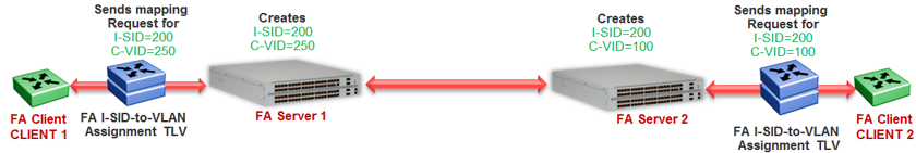
When Client 1 successfully attaches to FA Server 1, FA Server 1 creates a unique I-SID-to-VLAN mapping for Client 1 on its device. This mapping contains the I-SID and C-VID advertised by Client 1, using the FA Assignment TLV. For example, assume that Client 1 advertises I-SID 200 and C-VID 250.
Similarly, when Client 2 attaches to FA Server 2, FA Server 2 creates an I-SID-to-VLAN mapping for Client 2 on its device with, for example, I-SID 200 and C-VID 100. This is depicted in the following figure.
When data traffic ingresses FA Server 1 at the FA-enabled port 1/1, it contains the C-VID of Client 1, which is, 250. The data is VLAN-encapsulated at this stage. As traffic egresses FA Server 1 into the SPB cloud, it is encapsulated with the ELAN I-SID created on FA Server 1 on behalf of Client 1, that is I-SID 200. The traffic is now MiM encapsulated with I-SID 200.
The following figure depicts VLAN encapsulation of data traffic from the FA Client to the FA Server (at either end of the SPB cloud) and its MiM encapsulation as it traverses the SPB cloud.
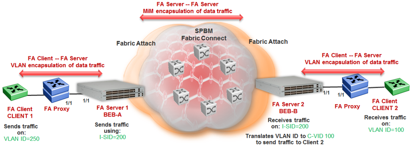
As traffic exits the SPB cloud and ingresses the remote FA Server 2, it continues to be MiM encapsulated with I-SID 200.
At FA Server 2, the MiM traffic is decapsulated. Since the I-SID in the data packet matches the I-SID created on its device on behalf of Client 2, FA Server 2 prepares to send traffic to Client 2. At this stage, to successfully transmit the data traffic to Client 2, FA Server 2 must additionally know the C-VID that Client 2 expects traffic on. This information is obtained from the I-SID-to-VLAN mapping on FA Server 2 created on behalf of Client 2, which is C–VID 100. Thus FA Server 2 translates the C-VID in its data packets to this VLAN ID, and then passes it on to Client 2.
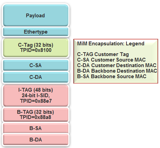
The following figure depicts the typical MiM encapsulation of a data packet. The B-DA and B-SA components indicated the system ID of the FA Server running SPB.