Use the information in this section to understand how to reduce the size of routing tables.
Classless interdomain routing (CIDR) is an addressing scheme (also known as supernetting) that eliminates the concept of classifying networks into class types. Earlier addressing schemes identified five classes of networks: Class A, Class B, Class C, Class D, and Class E. This document does not discuss Classes D (used for multicast) and E (reserved and currently not used).
Network 195.215.0.0, an illegal Class C network number, becomes a legal supernet when represented in CIDR notation as 195.215.0.0/16. The /16 is the prefix length and expresses the explicit mask that CIDR requires. In this case, the addition of the prefix /16 indicates that the subnet mask consists of 16 bits (counting from the left).
Using this method, supernet 195.215.0.0/16 represents 195.215.0.0 255.255.0.0. The following table shows the conversion of prefix length to subnet mask.
|
Prefix |
Dotted-decimal |
Binary |
Network class |
|---|---|---|---|
|
/1 |
128.0.0.0 |
1000 0000 0000 0000 0000 0000 0000 0000 |
128 Class A |
|
/2 |
192.0.0.0 |
1100 0000 0000 0000 0000 0000 0000 0000 |
64 Class A |
|
/3 |
224.0.0.0 |
1110 0000 0000 0000 0000 0000 0000 0000 |
32 Class A |
|
/4 |
240.0.0.0 |
1111 0000 0000 0000 0000 0000 0000 0000 |
16 Class A |
|
/5 |
248.0.0.0 |
1111 1000 0000 0000 0000 0000 0000 0000 |
8 Class A |
|
/6 |
252.0.0.0 |
1111 1100 0000 0000 0000 0000 0000 0000 |
4 Class A |
|
/7 |
254.0.0.0 |
1111 1110 0000 0000 0000 0000 0000 0000 |
2 Class A |
|
/8 |
255.0.0.0 |
1111 1111 0000 0000 0000 0000 0000 0000 |
1 Class A or 256 Class B |
|
/9 |
255.128.0.0 |
1111 1111 1000 0000 0000 0000 0000 0000 |
128 Class B |
|
/10 |
255.192.0.0 |
1111 1111 1100 0000 0000 0000 0000 0000 |
64 Class B |
|
/11 |
255.224.0.0 |
1111 1111 1110 0000 0000 0000 0000 0000 |
32 Class B |
|
/12 |
255.240.0.0 |
1111 1111 1111 0000 0000 0000 0000 0000 |
16 Class B |
|
/13 |
255.248.0.0 |
1111 1111 1111 1000 0000 0000 0000 0000 |
8 Class B |
|
/14 |
255.252.0.0 |
1111 1111 1111 1100 0000 0000 0000 0000 |
4 Class B |
|
/15 |
255.254.0.0 |
1111 1111 1111 1110 0000 0000 0000 0000 |
2 Class B |
|
/16 |
255.225.0.0 |
1111 1111 1111 1111 0000 0000 0000 0000 |
1 Class B or 256 Class C |
|
/17 |
255.255.128.0 |
1111 1111 1111 1111 1000 0000 0000 0000 |
128 Class C |
|
/18 |
255.255.192.0 |
1111 1111 1111 1111 1100 0000 0000 0000 |
64 Class C |
|
/19 |
255.255.224.0 |
1111 1111 1111 1111 1110 0000 0000 0000 |
32 Class C |
|
/20 |
255.255.240.0 |
1111 1111 1111 1111 1111 0000 0000 0000 |
16 Class C |
|
/21 |
255.255.248.0 |
1111 1111 1111 1111 1111 1000 0000 0000 |
8 Class C |
|
/22 |
255.255.252.0 |
1111 1111 1111 1111 1111 1100 0000 0000 |
4 Class C |
|
/23 |
255.255.254.0 |
1111 1111 1111 1111 1111 1110 0000 0000 |
2 Class C |
|
/24 |
255.255.225.0 |
1111 1111 1111 1111 1111 1111 0000 0000 |
1 Class C |
Use CIDR to assign network prefixes of arbitrary lengths, as opposed to the obsolete class system, which assigned prefixes as even multiples of an octet.
For example, you can assign a single routing table supernet entry of 195.215.16/21 to represent 8 separate Class C network numbers: 195.215.16.0 through 195.215.23.0.
You can create a supernet address that covers an address range.
For example, to create a supernet address that covers an address range of 192.32.0.0 to 192.32.9.255, perform the following steps:
Convert the starting and ending address range from dotted-decimal notation to binary notation (see the following figure).
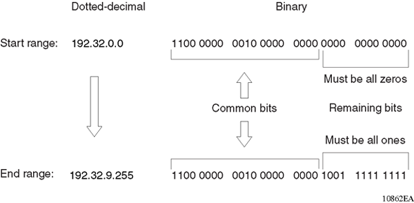
Locate the common bits in both ranges. Ensure that the remaining bits in the start range are zeros, and the remaining bits in the end range are all ones. In this example, the remaining bits in the end range are not all ones.
If the remaining bits in the end range are not all ones, you must recalculate to find the IP prefix that has only ones in the remaining bits in the end range.
Recalculate to find a network prefix that has all ones in the remaining end range bits (see the following figure). In this example, 192.32.7.255 is the closest IP prefix that matches the common bits for the start range.
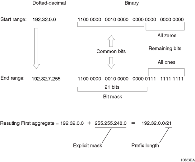
The 21 bits that match the common bits form the prefix length. The prefix length is the number of binary bits that form the explicit mask (in dotted-decimal notation) for this IP prefix.
The remaining aggregate is formed from 192.32.8.0 to the end range, 192.32.9.255.
As shown in First aggregate and prefix length, the resulting first aggregate 192.32.0.0/21 represents all of the IP prefixes from 192.32.0.0 to 192.32.7.255.
The following figure shows the results after forming the remaining aggregate from 192.32.9.0 to the end range, 192.32.9.255.
The resulting aggregate 192.32.8.0/23 represents all of the IP prefixes from 192.32.8.0 to 192.32.9.255.

The final result of calculating the supernet address that ranges from 192.32.00 to 192.32.9.255 is as follows:
192.32.0.0 (with mask) 255.255.248.0 = 192.32.0.0/21
192.32.8.0 (with mask) 255.255.254.0 = 192.32.8.0/23
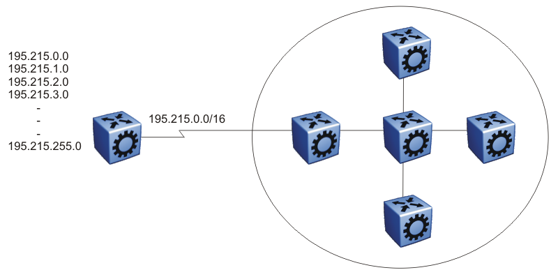
Eliminating the idea of network classes provides an easy method to aggregate routes. Rather than advertise a separate route for each destination network in a supernet, BGP uses a supernet address to advertise a single route (called an aggregate route) that represents all the destinations. CIDR also reduces the size of the routing tables used to store advertised IP routes.
The following figure shows an example of route aggregation using CIDR. In this example, a single supernet address 195.215.0.0/16 advertises 256 separate Class C network numbers 195.215.0.0 through 195.215.255.0.
A BGP router configured for iBGP establishes a peer-to-peer session with every other iBGP speaker in the AS. In an AS with a large number of iBGP speakers, this full-mesh topology can result in high bandwidth and maintenance costs.

Note
Confederations are not supported on iBGP for non-default VRFs.
As shown in the following example, a full-mesh topology for an AS with 50 iBGP speakers requires 1225 internal peer-to-peer connections:
Example:
n x (n-1)/2 = n iBGP sessions
where:
50 x (50-1)/2 = 1225 number of unique iBGP sessions
You can reduce the high bandwidth and maintenance costs associated with a large full-mesh topology by dividing the AS into multiple smaller autonomous systems (sub-autonomous systems), and then group them into a single confederation (see the following figure).

As shown in the preceding figure, each sub-AS is fully meshed within itself and has eBGP sessions with other sub-autonomous systems in the same confederation.
Although the peers in different autonomous systems have eBGP sessions with the various sub-AS peers, they preserve the next-hop, Multi-Exit Discriminator (MED), and local preference information and exchange routing updates as if they were iBGP peers. All of the autonomous systems retain a single interior gateway protocol (IGP). When the confederation uses its own confederation identifier, the system displays the group of sub-autonomous systems as a single AS (with the confederation identifier as the AS number).
Another way to reduce the iBGP mesh inherent in an AS with a large number of iBGP speakers is to configure a route reflector. Using this method, when an iBGP speaker needs to communicate with other BGP speakers in the AS, the speaker establishes a single peer-to-peer route reflector client session with the iBGP route reflector.
Note
Route reflectors are not supported on iBGP for non-default VRFs.
In an AS, more than one route reflector cluster can exist and more than one route reflector in a cluster. When more than one reflector exists in a cluster, take care to prevent route loops.
The following figure shows a simple iBGP configuration with three iBGP speakers (routers A, B, and C). Without route reflectors, after Router A receives an advertised route from an external neighbor, it must advertise the route to Routers B and C.

Routers B and C do not readvertise the iBGP learned routes to other iBGP speakers. BGP does not allow routers to pass routes learned from internal neighbors on to other internal neighbors, which avoids routing information loops.
As shown in the following figure, when you configure an internal BGP peer (Router B) as a route reflector, all of the iBGP speakers do not need to be fully meshed. In this case, the assigned route reflector passes iBGP learned routes to a set of iBGP neighbors.
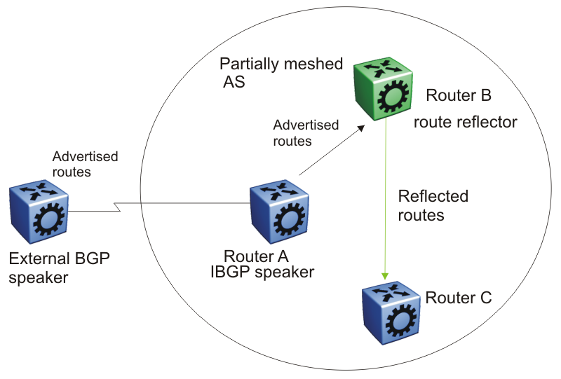
After Router B, the route reflector, receives routes from Router A (the iBGP speaker), it advertises them to router C. Conversely, after the route reflector receives routes from internal peers, it advertises those routes to Router A. Routers A and C do not need an iBGP session.
Route reflectors separate internal peers into two groups: client peers and nonclient peers. The route reflector and its clients form a cluster. The client peers in the cluster do not need to be fully meshed, and do not communicate with iBGP speakers outside their cluster. Nonclient peers must be fully meshed with each other.
The following figure shows a cluster, where Router A is the route reflector in a cluster with client routers B, C, and D. Routers E, F, and G are fully meshed, nonclient routers.
