Typical customer deployments require redundancy all the way to the access side of the network. IP Multicast over Fabric Connect supports switch clustering, Split Multilink Trunking (SMLT) technology, at the edge of the SPBM fabric, providing redundancy to the access Layer 2 switch where you can attach multicast senders and receivers. Typical SPBM fabric deployments use two or more B-VLANs for Equal Cost Multipath (ECMP) and resiliency. For simplicity in understanding how the SPBM network works, assume that there are two B-VLANs (primary and secondary).
The following figure shows how multicast senders and receivers connect to the SPBM cloud using BEBs.
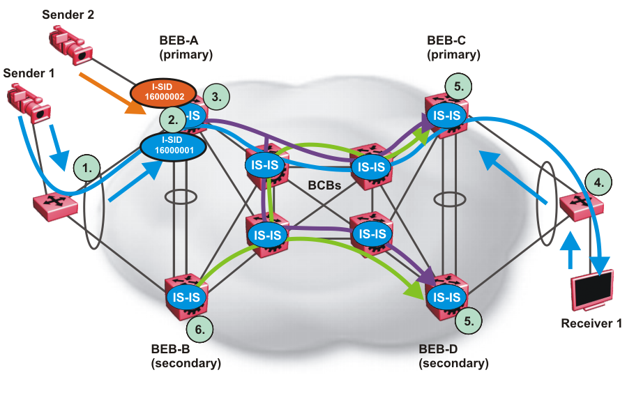
The edge switch hashes the sender multicast data to a specific MLT link.
A multicast stream received at the edge of the SPBM fabric is mapped to a dedicated multicast data I-SID.
For the non-SMLT attached sender 2, the stream is hashed to the primary or secondary B-VLAN based on whether the data I-SID is even or odd numbered. For the SMLT attached to sender 1, IS-IS advertises the stream to the rest of the fabric on the primary B-VLAN and synchronizes information to the vIST peer.
The edge switch hashes the receiver IGMP join to a specific MLT link.
Both BEBs on both B-VIDs advertise the IGMP join.
The multicast tree is built for (S1,G1), which is rooted in the primary sender BEB. The multicast tree is built for (S1,G1), which is rooted in the secondary sender BEB.
IGMP Snooping is widely used on Layer 2 access switches to prune multicast traffic. In IP Multicast over Fabric Connect, BEBs are the IGMP Queriers, therefore access switches forward multicast data from the senders as well as IGMP control messages from receivers to the BEBs.
When a sender transmits multicast data to the Layer 2 access switch that has an MLT to the switch cluster, it is hashed towards one or the other BEBs in the switch cluster. The receiving BEB allocates a data I-SID and sends a TLV update on either the primary B-VLAN or the secondary B-VLAN, depending on whether the BEB is the primary or secondary switch. The primary switch uses the primary B-VLAN, whereas, the secondary switch uses the secondary B-VLAN. This information is propagated through the SPBM fabric so all BEBs are aware of this stream availability.
The sender information is also synchronized over the vIST to the peer switch. Then the peer switch allocates a data I-SID for the multicast stream and sends a TLV update on the appropriate B-VLAN to announce the availability of the stream. The data I-SIDs allocated by the primary and secondary switch cluster peers may be the same or different, as they are allocated independently by each switch.

Note
If a sender attaches to only one BEB in a switch cluster, the sender information is not synchronized over the vIST because it is not SMLT attached. The sender information is advertised, and data is sent on either the primary or secondary B-VLAN. The odd-numbered data I-SIDs use the primary B-VLAN, and the even-numbered data I-SIDs use the secondary B-VLAN. The same hashing rules apply to the forwarding of multicast data.
When a receiver sends an IGMP join message to the Layer 2 access switch that has an MLT to the switch cluster, it is hashed towards one or the other BEBs in the switch cluster. The receiving BEB queries the IS-IS Link State Database (LSDB) to check if a sender exists for the requested stream within the scope of the receiver.
If the requested stream does not exist, the BEB keeps the IGMP information but no further action is taken. If the requested stream exists, the BEB sends an IS-IS Link State Packet (LSP), with TLV update information, for both primary and secondary B-VLANs to its neighbors to inform them of the presence of a receiver. The BEB propagates this information through LSPs through the SPBM cloud. The receiver information is also synchronized over the vIST to the peer switch. The peer switch then queries its IS-IS Link State Database (LSDB) and, if the requested stream exists, it sends an IS-IS LSP, with a TLV update, for both primary and secondary B-VLANs to its neighbors to inform them of the presence of the receiver.
IS-IS uses these TLV updates in LSPs to create multicast shortest path first trees in the SPBM fabric. IS-IS creates a shortest path first tree for the primary and secondary B-VLANs, but only one of the B-VLANs transports multicast data with the other in active standby in case of failures at the SPBM edge. After IS-IS creates the trees, multicast data flows between senders and receivers.
Primary SMLT peer BEB always advertises the streams it receives, and sends data for them on the primary B-VLAN.
Secondary SMLT peer BEB always advertises the streams it receives, and sends data for them on the secondary B-VLAN.
Non-SMLT BEBs or SMLT BEBs with single attached senders advertise streams, and send data on the primary or secondary B-VLAN based on hash criteria (odd-numbered data I-SIDs use primary B-VLAN; even-numbered data I-SIDs use secondary B-VLAN).
The primary SMLT peer BEB that receives multicast data on the primary B-VLAN sends it to both SMLT and non-SMLT SPBM access (UNI) links.
The primary SMLT peer BEB that receives multicast data on the secondary B-VLAN sends it to non-SMLT SPBM access (UNI) links only.
The secondary SMLT peer BEB that receives multicast data on primary B-VLAN sends it to non-SMLT SPBM access (UNI) links only.
The secondary SMLT peer BEB that receives multicast data on secondary B-VLAN sends data to both SMLT and non-SMLT SPBM access (UNI) links.
The non-SMLT BEB that receives multicast data on primary or secondary B-VLAN sends data to all SPBM access (UNI) links.
For C-VLANs in an SMLT environment, the vIST ports are not part of the VLAN.
The vIST peer with the higher IP address sends the queries out all SMLT and non-SMLT ports on SPBM access links.
The vIST peer with the lower IP address only sends out queries on its non-SMLT ports. This includes SMLT ports whose remote ports are down (SMLT state of ‘norm‘).
With the existence of an vIST peer with a higher IP address and an vIST peer with a lower IP address, it means two queriers exist within the C-VLAN. Having two queriers poses no problems in this SPB environment, as all SMLT access devices see the vIST peer with the higher IP address as the querier, and non-SMLT access devices see the directly connected vIST peer as the querier. Non-SMLT access devices that connect on either side of the vIST peers can talk to each other using the SPBM cloud.