The following diagrams illustrate the components on the front panels of the VSP 4900 switches.
The following diagram illustrates the components of the front panel of the VSP4900-48P switch. Slot 1 is used for the 48 fixed ports and slot 2 is used for Versatile Interface Module (VIM) ports, if a VIM is installed in the VIM slot.
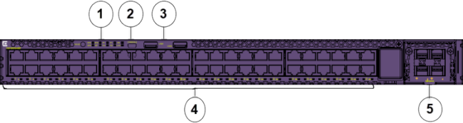
Mode button for port LED control. Port LED mode indicators (SYS, SPD). Switch LEDs for system power (P1, P2) and fans (F1, F2, F3). System Locator LED (LOC).

Note
Note: STK and BT port LED mode indicators are not supported.
One USB micro B console port. An alternative RJ-45 console port is provided on the back panel (not shown).
Two USB ports, for removable storage.
48 10/100/1000 Mbps RJ-45 Ethernet ports that provide 802.3at PoE+. LEDs that indicate the port activity and statuses are below the ports.
VIM slot (shown with VIM installed). Port numbering depends on the type of VIM installed in the slot. For more information about VIM modules, see VSP 4900 Series Switches: Hardware Installation Guide.
The back panel (not shown) includes an RJ-45 out of band (OOB) management port, an RJ-45 console port, and hot-swappable power supply and fan units.
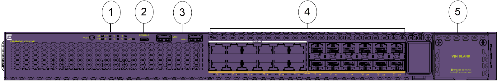
The following diagram illustrates the components on the front panel of the VSP4900-24XE switch. Slot 1 is used for the 24 fixed ports and slot 2 is used for Versatile Interface Module (VIM) ports, if a VIM is installed in the VIM slot.
Mode button for port LED control. Port LED mode indicators (SYS, SPD, STK and BT). Switch LEDs for system power (P1, P2) and fans (F1, F2, F3). System Locator LED (LOC).
One USB micro B console port. An alternative RJ-45 console port is provided on the back panel (not shown).
Two USB ports, for removable storage.
24 1/10 Gbps ports. LEDs that indicate the port activity and statuses are below the ports.
VIM slot. Port numbering depends on the type of VIM installed in the slot. For more information about VIM modules, see VSP 4900 Series Switches: Hardware Installation Guide.
The back panel (not shown) includes an RJ-45 out of band (OOB) management port, an RJ-45 console port, Solid State Drive (SSD) slot, and hot-swappable power supply and fan units.
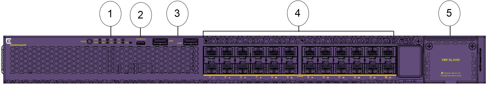
The following diagram illustrates the components on the front panel of the VSP4900-12MXU-12XE switch. Slot 1 is used for the 24 fixed ports and slot 2 is used for Versatile Interface Module (VIM) ports, if a VIM is installed in the VIM slot.
Mode button for port LED control. Port LED mode indicators (SYS, SPD, STK and BT). Switch LEDs for system power (P1, P2) and fans (F1, F2, F3). System Locator LED (LOC).
One USB micro B console port. An alternative RJ-45 console port is provided on the back panel (not shown).
Two USB ports, for removable storage.
Ports 1 to 12 are 100 Mbps and 1/2.5/5/10 Gbps RJ-45 ports that provide PoE (60W) and ports 13-24 are 1/10 Gbps ports. LEDs that indicate the port activity and statuses are below the ports.
VIM slot. Port numbering depends on the type of VIM installed in the slot. For more information about VIM modules, see VSP 4900 Series Switches: Hardware Installation Guide.
The back panel (not shown) includes an RJ-45 out of band (OOB) management port, an RJ-45 console port, SSD slot, and hot-swappable power supply and fan units.
The following diagram illustrates the components on the front panel of the VSP4900-24S switch. Slot 1 is used for the 24 fixed ports and slot 2 is used for Versatile Interface Module (VIM) ports, if a VIM is installed in the VIM slot.
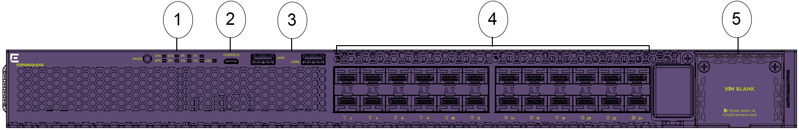
Mode button for port LED control. Port LED mode indicators (SYS, SPD, STK and BT). Switch LEDs for system power (P1, P2) and fans (F1, F2, F3). System Locator LED (LOC).
One USB micro B console port. An alternative RJ-45 console port is provided on the back panel (not shown).
Two USB ports, for removable storage.
24 1 Gbps ports. LEDs that indicate the port activity and statuses are below the ports.
VIM slot. Port numbering depends on the type of VIM installed in the slot. For more information about VIM modules, see VSP 4900 Series Switches: Hardware Installation Guide.
The back panel (not shown) includes an RJ-45 out of band (OOB) management port, an RJ-45 console port, and hot-swappable power supply and fan units.