The switch supports Network Load Balancing (NLB) in the following topologies.
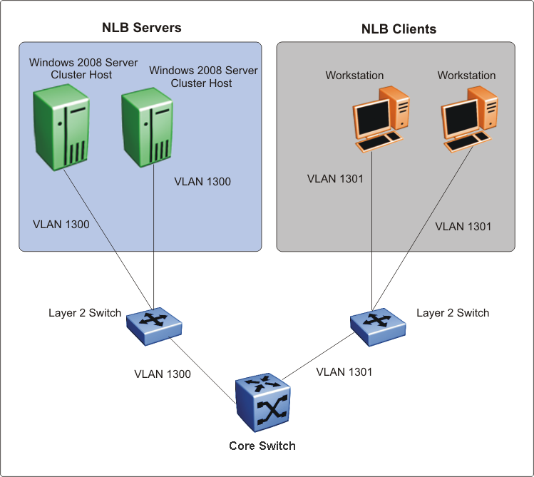
The switch supports NLB when the NLB Cluster connections use a different physical port on the switch than the NLB clients.
The following figure illustrates this configuration where the NLB Server and the NLB Client workstations connect to different aggregation switches, which connect to the switch using different VLANs and different ports.
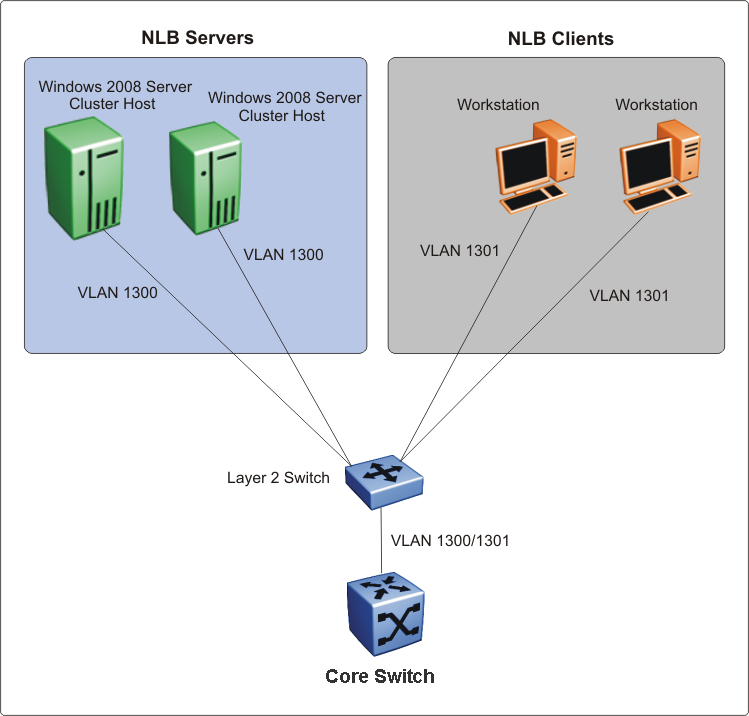
The switch also supports the following topology where the NLB Server and the NLB Client workstations connect to the same aggregation switch and then connect to the switch using the same port.

Note
The switch supports Layer 3 routing between an NLB-enabled VLAN and another VLAN on the same port.
The switch supports NLB in the following other topologies:
NLB cluster hosts and clients are connected to Layer 2 Ethernet switches that are SMLT connected to the SMLT cluster.
NLB cluster hosts are directly connected and distributed between the switches and the clients are connected to Layer 2 Ethernet switch that is SMLT connected to the SMLT cluster.
NLB cluster hosts and clients are directly connected and distributed between the switches in the SMLT cluster.
NLB cluster hosts and clients are connected to Layer 2 Ethernet switches that are SMLT connected to the SMLT cluster core.
Note
For more information on the above topologies, see Technical Configuration Guide for Microsoft Network Load Balancing.