The Rapid Spanning Tree Protocol (RSTP or IEEE 802.1w) reduces the recovery time after a network breakdown. It also maintains backward compatibility with IEEE 802.1d (the spanning tree implementation prior to RSTP). In certain configurations, the recovery time of RSTP can be reduced to less than 1 second. RSTP also reduces the amount of flooding in the network by enhancing the way Topology Change Notification (TCN) packets are generated.
With Multiple Spanning Tree Protocol (MSTP or IEEE 802.1s), you can configure multiple instances or Spanning Tree groups on the same device. Each instance or Spanning Tree group can include one or more VLANs.
By using RSTP and MSTP, the switch achieves the following:
reduces convergence time after a topology change (from 30 seconds to less than 1 or 2 seconds)
eliminates unnecessary flushing of the MAC database and the flooding of traffic to the network
creates backward compatibility with classic 802.1d switches
creates support for 64 instances of spanning tree in MSTP mode
The following sections relate to RSTP and MSTP:
RSTP provides a parameter called ForceVersion to provide backward compatibility with standard STP. A user can configure a port in either STP-compatible mode or RSTP mode:
An STP-compatible port transmits and receives only STP Bridge Protocol Data Units (BPDUs). An RSTP BPDU that the port receives in this mode is discarded.
An RSTP-compatible port transmits and receives only RSTP BPDUs. If an RSTP port receives an STP BPDU, it becomes an STP port. User intervention is required to change this port back to RSTP mode. This process is called Port Protocol Migration.

Note
You must configure protocol migration to true on all spanning-tree enabled interfaces when you change the spanning tree version from STP-compatible to MSTP for those interfaces to work in the proper mode.
Before implement MSTP or RSTP you must be aware of the following:
The default mode is MSTP. A special boot configuration flag identifies the mode.
You can lose your configuration if you change the spanning tree mode from MSTP to RSTP and the configuration file contains VLANs configured with MSTI greater than 0. RSTP only supports VLANs configured with the default instance 0.
For best interoperability results, contact your vendor representative.
RSTP is an enhanced version of STP. These two protocols have almost the same parameters.
The following table lists the differences in port roles for STP and RSTP. STP supports two port roles, while RSTP supports four port roles.
|
Port Role |
STP |
RSTP |
Description |
|---|---|---|---|
|
Root |
Yes |
Yes |
This port receives a better BPDU than its own and has the best path to reach the Root. The root port is in Forwarding state. The root port and designated ports can be in the Discarding state before they go to root forwarding. |
|
Designated |
Yes |
Yes |
This port has the best BPDU on the segment. The designated port is in the Forwarding state. |
|
Alternate |
No |
Yes |
This port receives a better BPDU than its own BPDU, and a root port exists within the same device. The alternate port is in the Discarding state. |
|
Backup |
No |
Yes |
This port receives a better BPDU than its own BPDU, and this BPDU is from another port within the same device. The backup port is in the Discarding state. |
MSTP and RSTP root forwarding roles are as follows:
The port that receives the best path BPDU on a device is the root port, and is referred to as a Root Forwarding (RF) port. This is the port that is the closest to the root bridge in terms of path cost.
The spanning tree algorithm elects a single root bridge in a bridged network. With MSTP, a root bridge is selected for the Common and Internal Spanning Tree (CIST). A root bridge is selected for the region, and a root bridge is selected for each spanning tree instance.
The root bridge is the only bridge in a network that does not have root ports; all ports on a root bridge are Designated Forwarding (DF).
Only one path towards a root bridge can exist on a given segment; otherwise, loops can occur.
MSTP and RSTP designated forwarding roles are as follows:
All bridges connected on a segment monitor the BPDUs of all other bridges. The bridge that sends the best BPDU is the root bridge for the segment.
The corresponding port on the bridge is referred to as a Designated Forwarding Port.
MSTP and RSTP alternate blocking roles are as follows:
A blocked port is defined as not being the designated or root port. An alternate port provides an alternate path to the root and can replace the root port if it fails.
An alternate blocked port is a port that is blocked because it received better path cost BPDUs from another bridge.
MSTP and RSTP backup blocking roles are as follows:
A backup port receives the more useful BPDUs from the bridge on which the port exists.
RSTP uses a parameter called the edge port. After a port connects to a nonswitch device, such as a PC or a workstation, it must be configured as an edge port. An active edge port enters the forwarding state without delay. An edge port becomes a nonedge port if it receives a BPDU.
RSTP and MSTP path cost values support a wide range of link speeds. The following table lists the path cost values.
|
Link speed |
Value |
|---|---|
|
Less than or equal to 100 Kbps 1 Mbps 10 Mbps 100 Mbps |
200 000 000 20 000 000 2 000 000 200 000 |
|
1 Gbps 10 Gbps 100 Gbps |
20 000 2000 200 |
|
1 Tbps 10 Tbps |
20 2 |
The following section describes the negotiation process between switches that takes place before PCs can exchange data (see the following figure).
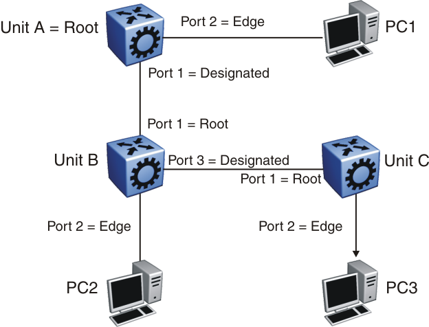
After turning on, all ports assume the role of designated ports. All ports are in the discarding state except edge ports. Edge ports go directly into the forwarding state without delay.
Unit A port 1 and Unit B port 1 exchange BPDUs. Unit A knows that it is the root and that Unit A port 1 is the designated port. Unit B learns that Unit A has higher priority. Unit B port 1 becomes the root port. Both Unit A port 1 and Unit B port 1 are still in the discarding state.
Unit A starts the negotiation process by sending a BPDU with the proposal bit set.
Unit B receives the proposal BPDU and configures its nonedge ports to discarding state. This operation occurs during the synchronization process.
Unit B sends a BPDU to Unit A with the agreement bit set.
Unit A configures port 1 to the forwarding state, and Unit B configures port 1 to the forwarding state. PC 1 and PC 2 can now communicate. The negotiation process now moves on to Unit B port 3 and its partner port. PC 3 cannot exchange data with either PC 1 or PC 2 until the negotiation process between Unit B and Unit C finishes.
The RSTP convergence time depends on how quickly the switchil recan exchange BPDUs during the negotiation process, and on the number of switches in the network.