Use CLIP to configure a resilient RP and BSR for a PIM network. When you configure an RP or BSR on a regular interface, if it becomes nonoperational, the RP and BSR also become nonoperational. This status results in the election of other redundant RPs and BSRs, and can disrupt IP multicast traffic flow in the network. As a best practice for multicast networks design, always configure the RP and BSR on a CLIP interface to prevent a single interface failure from causing these entities to fail.
Also, configure redundant RPs and BSRs on different switches such that these entities are on CLIP interfaces. For the successful setup of multicast streams, ensure that a unicast route exists to all CLIP interfaces from all locations in the network. A unicast route is mandatory because, for proper RP learning and stream setup on the shared RP tree, every switch in the network needs to reach the RP and BSR. You can use PIM-SM CLIP interfaces only for RP and BSR configurations, and are not intended for other purposes.
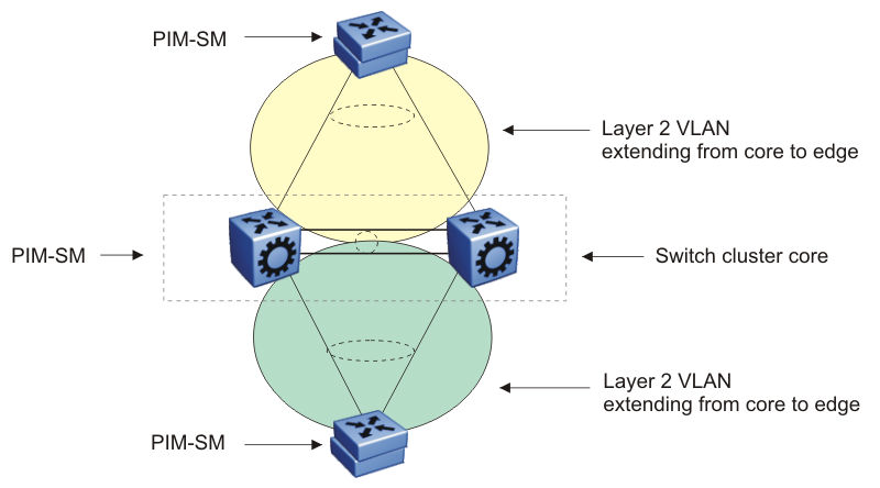
Do not configure non-SMLT IGMP leaf ports on a router to be one of the redundant RP CLIP devices. It is possible that these IGMP hosts can become isolated from the multicast data stream(s).
Consider an example where one of the peers, vIST-A, is the PIM DR for the source VLAN, and the source data is hashed to vIST-A from the Layer 2 source edge. vIST-A forwards traffic to the receiver edge using the SMLT link from vIST-A to the receiver edge. If the SMLT link fails, vIST-A does not forward traffic over the vIST link to vIST-B, and the receiver edge does receive the data.
In this topology, the receiver edge sends an IGMP membership report for a group, which is recorded on both vIST peers as an IGMP LEAF on the receiver SMLT port on the receiver VLAN.
Because both of the vIST peers are the RP for the group, they do not send a (*,g) PIM JOIN message toward the other RP. The (*,g) PIM mroute does not record the vIST port as a JOIN port on either vIST device. The PIM (*,g) mroute records only a LEAF on the SMLT receiver port.
Because the source is local (Layer 2 edge), there is no PIM (s,g) JOIN message toward the source and the (s,g) PIM mroute does not record the vIST port as a JOIN port on either vIST device. The PIM (s,g) mroute records only a LEAF on the SMLT receiver port.
If the source is hashed to vIST-A, the PIM DR for the incoming VLAN, traffic is forwarded to the receiver correctly. vIST-A does not forward traffic over the vIST to vIST-B, because no JOIN exists on the vIST port. If the receiver SMLT link from the vIST-A peer is down, the traffic is not forwarded to vIST-B, and is not received by the receiver edge. Traffic resumes after the link is restored. If the source data hashes to the non-DR peer, vIST-B, no problem occurs because the non-DR always forwards traffic to the DR.
A similar situation exists in this topology when vIST-A is both the RP and the DR for the Layer 2 receiver edge. The vIST port is not in the outgoing port list because there is no JOIN message from the peer toward the source (which is not PIM enabled). Therefore, if the SMLT link from vIST-A to the receiver edge is down, the system does not forward traffic to the peer vIST-B and down to the receiver.
You can avoid the preceding problems with this topology by performing one of the following actions:
Enable PIM on the source edge.
The vIST peers send PIM joins toward the source and the JOIN is recorded on the vIST port for the (s,g). Data is forwarded to the peer.
Do not configure dual redundant RPs.
One vIST peer is the RP for a group.
Do not configure one vIST peer as both the DR for the source VLAN and the RP for the receiver group.
The system forwards the traffic to the RP or to the DR, depending on which peer receives the source, and, if the SMLT link to the receiver goes down there will be no data loss.