SPBM supports data centers with IP shortcuts, Layer 2 VSNs, or Layer 3 VSNs. If you use vMotion, you must use Layer 2 between data centers (Layer 2 VSN). With Layer 2 VSNs, you can add IP addresses to the VLAN on both data centers and run Virtual Router Redundancy Protocol (VRRP) between them to allow the ESX server to route to the rest of the network.
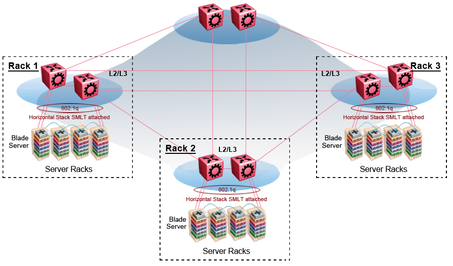
The following figure shows an SPBM topology of a large data center. This figure represents a full-mesh data center fabric using SPBM for storage over Ethernet. This topology is optimized for storage transport because traffic never travels more than two hops.

Note
As a best practice, use a two-tier, full-mesh topology for large data centers.
In a traditional data center configuration, the traffic flows into the network to a VM and out of the network in almost a direct path.
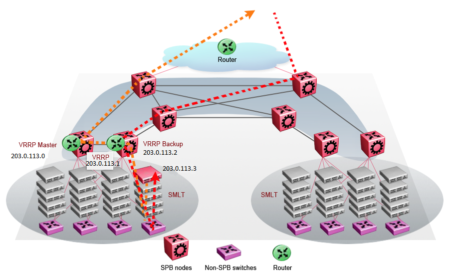
The following figure shows an example of a traditional data center with VRRP configured. Because end stations are often configured with a static default gateway IP address, a loss of the default gateway router causes a loss of connectivity to the remote networks. VRRP eliminates the single point of failure that can occur when the single static default gateway router for an end station is lost.
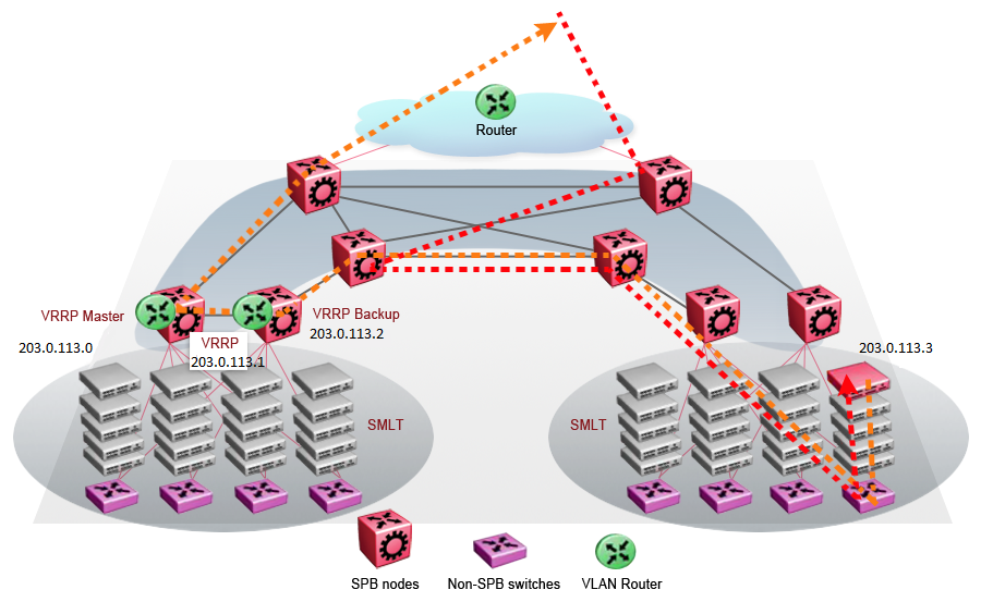
A VM is a virtual server. When you move a VM, the virtual server is moved as is. This action means that the IP addresses of that server remain the same after the server is moved from one data center to the other. This in turn dictates that the same IP subnet (and hence VLAN) exist in both data centers.
In the following figure, the VM moved from the data center on the left to the data center on the right. To ensure a seamless transition that is transparent to the user, the VM retains its network connections through the default gateway. This method works, but it adds more hops to all traffic. As you can see in the figure, one VM move results in a complicated traffic path. Multiply this with many moves and soon the network look like a tangled mess that is very inefficient, difficult to maintain, and almost impossible to troubleshoot.
Two features make a data center optimized:
VLAN routers in the Layer 2 domain (green icons)
VRRP BackupMaster
The VLAN routers use lookup tables to determine the best path to route incoming traffic (red dots) to the destination VM.
VRRP BackupMaster solves the problem of traffic congestion on the vIST. Because there can be only one VRRP Master, all other interfaces are in backup mode. In this case, all traffic is forwarded over the vIST link towards the primary VRRP switch. All traffic that arrives at the VRRP backup interface is forwarded, so there is not enough bandwidth on the vIST link to carry all the aggregated riser traffic. VRRP BackupMaster overcomes this issue by ensuring that the vIST trunk is not used in such a case for primary data forwarding. The VRRP BackupMaster acts as an IP router for packets destined for the logical VRRP IP address. All traffic is directly routed to the destined subnetwork and not through Layer 2 switches to the VRRP Master. This avoids potential limitation in the available vIST bandwidth.
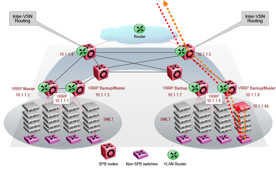
The following figure shows a solution that optimizes your network for bidirectional traffic flows. However, this solution turns two SPBM BCB nodes into BEBs where MAC and ARP learning will be enabled on the Inter-VSN routing interfaces. If you do not care about top-down traffic flows, you can omit the Inter-VSN routing interfaces on the SPBM BCB nodes. This makes the IP routed paths top-down less optimal, but the BCBs remain pure BCBs, thus simplifying core switch configurations.
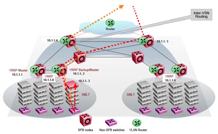
In the traditional data center, chaos resulted after many VMs were moved. In an optimized data center as shown in the following figure, the incoming traffic enters the Layer 2 domain where an edge switch uses Inter-VSN routing to attach an I-SID to a VLAN. The I-SID bridges traffic directly to the destination. With VRRP BackupMaster, the traffic no longer goes through the default gateway; it takes the most direct route in and out of the network.