Use OSPF to ensure that the switch can communicate with other OSPF routers. This section describes some general design considerations and presents a number of design scenarios for OSPF.
To determine OSPF link-state advertisement (LSA) limits:
Use the command show ip ospf area to determine the LSA_CNT and to obtain the number of LSAs for a given area.
Use the following formula to determine the number of areas. Ensure the total is less than 16,000 (16K):
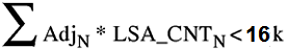
N = 1 to the number of areas for each switch
AdjN = number of adjacencies for each Area N
LSA_CNTN = number of LSAs for each Area N
For example, assume that a switch has a configuration of three areas with a total of 18 adjacencies and 1000 routes. This includes:
3 adjacencies with an LSA_CNT of 500 (Area 1)
10 adjacencies with an LSA_CNT of 1000 (Area 2)
5 adjacencies with an LSA_CNT of 200 (Area 3)
Calculate the number as follows:
3*500+10*1000+5*200=12.5K < 16K
This configuration ensures that the switch operates within accepted scalability limits.
Follow these additional OSPF guidelines:
OSPF timers must be consistent across the entire network.
Use OSPF area summarization to reduce routing table sizes.
Use OSPF passive interfaces to reduce the number of active neighbor adjacencies.
Use OSPF active interfaces only on intended route paths.
Configure wiring-closet subnets as OSPF passive interfaces unless they form a legitimate routing path for other routes.
Minimize the number of OSPF areas for each switch to avoid excessive shortest-path calculations.
The switch executes the Djikstra algorithm for each area separately.
Ensure that the OSPF dead interval is at least four times the OSPF hello-interval.
Use MD5 authentication on untrusted OSPF links.
Use stub or NSSAs as much as possible to reduce CPU overhead.
After you create an OSPF area route summary on an area border router, the summary route can attract traffic to the area border router for which the router does not have a specific destination route. Enabling ICMP unreachable-message generation on the switch can result in a high CPU utilization rate.
To avoid high CPU utilization, use a black-hole static route configuration. The black-hole static route is a route (equal to the OSPF summary route) with a next hop of 255.255.255.255. This configuration ensures that all traffic that does not have a specific next-hop destination route is dropped.
You can use OSPF routing in the core of a network.
The following figure describes a simple implementation of an OSPF network: enabling OSPF on two switches (S1 and S2) that are in the same subnet in one OSPF area.
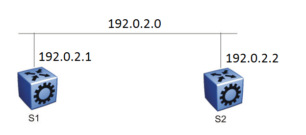
The routers in the preceding figure use the following configuration:
S1 has an OSPF router ID of 1.1.1.1, and the OSPF port uses an IP address of 192.0.2.1.
S2 has an OSPF router ID of 1.1.1.2, and the OSPF port uses an IP address of 192.0.2.2.
The general method to configure OSPF on each routing switch is:
Enable OSPF globally.
Enable IP forwarding on the switch.
Configure the IP address, subnet mask, and VLAN ID for the port.
Disable RIP on the port, if you do not need it.
Enable OSPF for the port.
After you configure S2, the two switches elect a designated router and a backup designated router. They exchange hello packets to synchronize their link state databases.
The following figure shows a configuration in which OSPF operates on three switches. OSPF performs routing on two subnets in one OSPF area. In this example, S1 directly connects to S2, and S3 directly connects to S2, but traffic between S1 and S3 is indirect, and passes through S2.

The routers in example 2 use the following configuration:
S1 has an OSPF router ID of 1.1.1.1, and the OSPF port uses an IP address of 192.0.2.1.
S2 has an OSPF router ID of 1.1.1.2, and two OSPF ports use IP addresses of 192.0.2.2 and 198.51.100.1.
S3 has an OSPF router ID of 1.1.1.3, and the OSPF port uses an IP address of 198.51.100.2.
The general method to configure OSPF on each routing switch is:
Enable OSPF globally.
Insert IP addresses, subnet masks, and VLAN IDs for the OSPF ports on S1 and S3, and for the two OSPF ports on S2. The two ports on S2 enable routing and establish the IP addresses related to the two networks.
Enable OSPF for each OSPF port allocated with an IP address.
After you configure all three switches for OSPF, they elect a designated router and a backup designated router for each subnet and exchange hello packets to synchronize their link-state databases.
The following figure shows an example where OSPF operates on two subnets in two OSPF areas. S2 becomes the area border router for both networks.
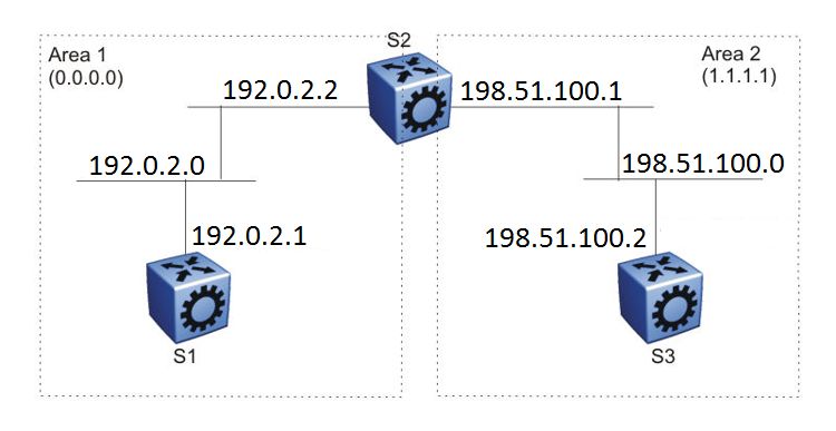
The routers in scenario 3 use the following configuration:
S1 has an OSPF router ID of 1.1.1.1. The OSPF port uses an IP address of 192.0.2.1, which is in OSPF area 1.
S2 has an OSPF router ID of 1.1.1.2. One port uses an IP address of 192.0.2.2, which is in OSPF area 1. The second OSPF port on S2 uses an IP address of 198.51.100.1, which is in OSPF area 2.
S3 has an OSPF router ID of 1.1.1.3. The OSPF port uses an IP address of 198.51.100.2, which is in OSPF area 2.
The general method to configure OSPF for this three-switch network is:
On all three switches, enable OSPF globally.
Configure OSPF on one network.
On S1, insert the IP address, subnet mask, and VLAN ID for the OSPF port. Enable OSPF on the port. On S2, insert the IP address, subnet mask, and VLAN ID for the OSPF port in area 1, and enable OSPF on the port. Both routable ports belong to the same network. Therefore, by default, both ports are in the same area.
Configure three OSPF areas for the network.
Configure OSPF on two additional ports in a second subnet.
Configure additional ports and verify that IP forwarding is enabled for each switch to ensure that routing can occur. On S2, insert the IP address, subnet mask, and VLAN ID for the OSPF port in area 2, and enable OSPF on the port. On S3, insert the IP address, subnet mask, and VLAN ID for the OSPF port, and enable OSPF on the port.
The three switches exchange hello packets.
In an environment with a mix of switches and routers from different vendors, you may need to manually modify the OSPF parameter RtrDeadInterval to 40 seconds.