The following diagrams illustrate the components on the front panels of the switches. For more information on hardware, see Installing the Virtual Services Platform 8000 Series.
The following figure illustrates the front view of the VSP 8284XSQ switch. There are 42 ports in Slot 1 on top, and 42 ports in Slot 2 on the bottom.
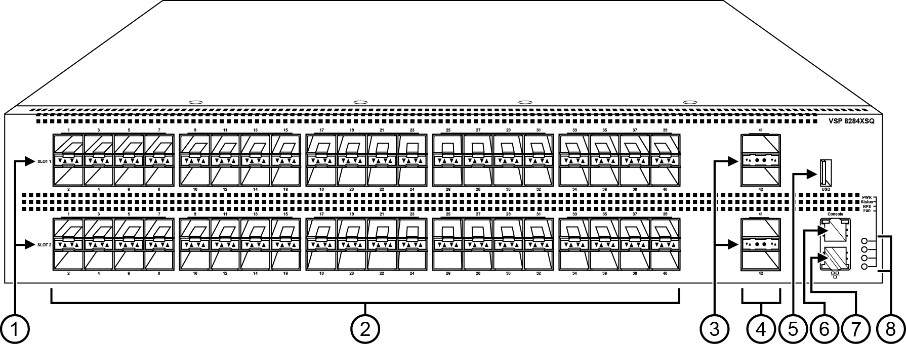
SFP+ port LEDs are in between the ports on each slot. The up arrows refer to the port above and the down arrows refer to the port below.
80 SFP+ ports that support 1G SFPs and 10G SFP+s.
40 ports in Slot 1 on top
40 ports in Slot 2 on the bottom
QSFP+ port LEDs are in between the ports on each slot. The up arrows refer to the port above and the down arrows refer to the port below.
Four QSFP+ ports: two in Slot 1 and two in Slot 2.
USB port
Console port (10101)
Management port — The LEDs are on the bottom of the port.
LEDs for system power (PWR), switch status (Status), redundant power supply (RPS), and fan modules(Fan).
The following figure illustrates the front view of the VSP 8400 Series switch.
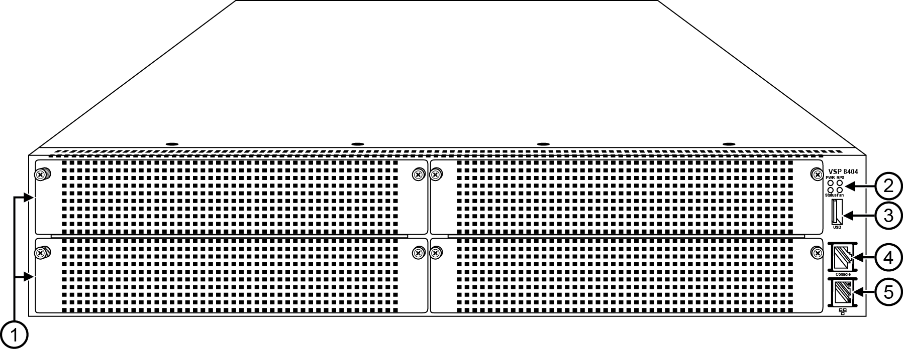
Looking at the front of the switch, slot numbering begins at the top row and increases from left to right. Slot 1 is the top-left slot; slot 2 is the top-right slot. Slot 3 is the bottom-left slot; slot 4 is the bottom-right slot.
Port numbering depends on the type of Ethernet Switch Module (ESM) installed in the slot. For more information about ESMs, see Installing the Virtual Services Platform 8000 Series.
Displays the four slots to install ESMs.
LEDs for system power (PWR), switch status (Status), redundant power supply (RPS), and fan modules (Fan).
USB port
Console port
OOB management port