The following figure shows a basic SPBM network topology, specifically a Layer 2 VSN. Switches A and D are the Backbone Edge Bridges (BEB) that provide the boundary between the customer VLANs (C-VLAN) and the Backbone. Switches B and C are the Backbone Core Bridges (BCB) that form the core of the SPBM network.
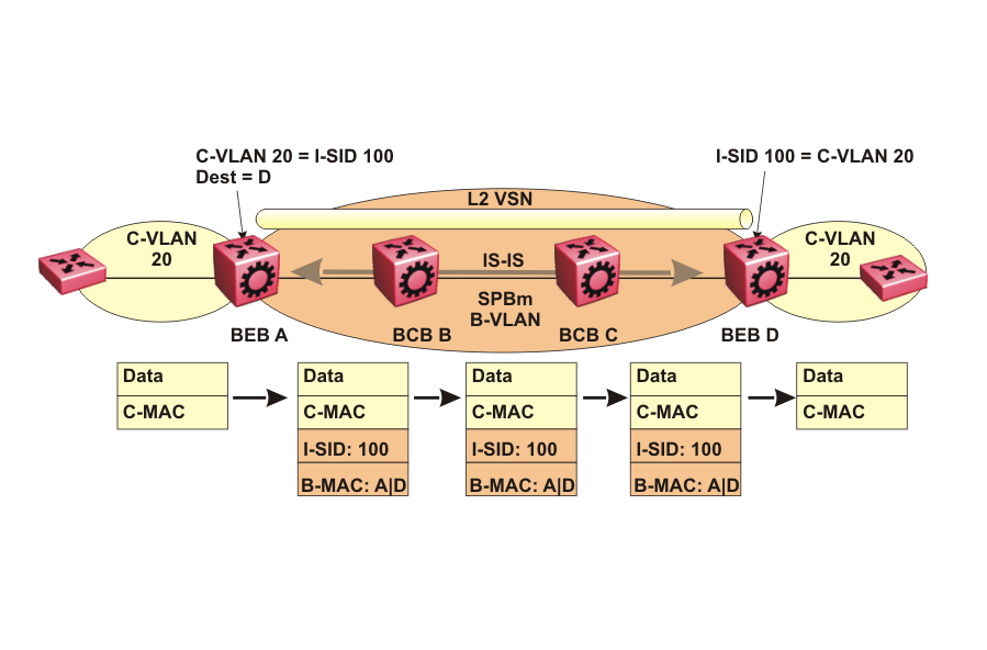
SPBM uses IS-IS in the core so that all BEBs and BCBs learn the IS-IS System-ID (B-MAC) of every other switch in the network. For example, BEB-A uses IS-IS to build an SPBM unicast forwarding table containing the B-MAC of switches BCB-B, BCB-C, and BEB-D.
The BEBs provide the boundary between the SPBM domain and the virtualized services domain. For a Layer 2 VSN service, the BEBs map a C-VLAN to an I-SID based on local service provisioning. Any BEB in the network that has the same I-SID configured can participate in the same Layer 2 VSN.
In this example, BEB A and BEB D are provisioned to associate C-VLAN 20 with I-SID 100. When BEB A receives traffic from C-VLAN 20 that must be forwarded to the far-end location, it performs a lookup and determines that C-VLAN 20 is associated with I-SID 100 and that BEB D is the destination for I-SID 100. BEB A then encapsulates the data and C-MAC header into a new B-MAC header, using its own nodal B-MAC: A as the source address and B-MAC: D as the destination address. BEB A then forwards the encapsulated traffic to BCB B.
To forward traffic in the core toward the destination node D, BCB B and BCB C perform Ethernet switching using the B-MAC information only.
At BEB D, the node strips off the B-MAC encapsulation, and performs a lookup to determine the destination for traffic with I-SID 100. BEB D identifies the destination on the C-VLAN header as C-VLAN 20 and forwards the packet to the appropriate destination VLAN and port.