Use the information in this section to help you configure BGP on your switch, which supports BGPv4 as described in RFC 1771.
The following list provides guidelines to successfully implement BGP:
BGP does not operate with an IP router in nonforwarding (host-only) mode. Make sure that the routers you want BGP to operate with are in forwarding mode.
If you use BGP for a multihomed AS (one that contains more than a single exit point), use OSPF for your IGP and BGP for your sole exterior gateway protocol, or use intra-AS iBGP routing.
If OSPF is the IGP, use the default OSPF tag construction. Using EGP or modifying the OSPF tags makes network administration and proper configuration of BGP path attributes difficult.
For routers that support both BGP and OSPF, the OSPF router ID and the BGP identifier must be the same IP address. The BGP router ID automatically uses the OSPF router ID.
In configurations where BGP speakers reside on routers that have multiple network connections over multiple IP interfaces (the typical case for iBGP speakers), consider using the address of the circuitless (virtual) IP interface as the local peer address. In this configuration, you ensure that BGP is reachable as long as an active circuit exists on the router.
By default, BGP speakers do not advertise or inject routes into the IGP. You must configure route policies to enable route advertisement.
Coordinate routing policies among all BGP speakers within an AS so that every BGP border router within an AS constructs the same path attributes for an external path.
Configure accept and announce policies on all iBGP connections to accept and propagate all routes. Make consistent routing policy decisions on external BGP connections.
You must configure the following minimum parameters:
router ID
local AS number
enable BGP globally
BGP neighbor peer session: remote IP addresses
enable BGP peers
When you use both BGP and OSPF, the OSPF and BGP router ID must be the same.
The router ID must be a valid IP address of an IP interface on the router or a CLIP address. BGP update messages use this IP address. By default, the BGP router ID automatically uses the OSPF router ID.
You cannot configure the BGP router ID if you configure BGP before you configured the OSPF router ID. You must first disable BGP, configure the OSPF route ID, and then enable BGP globally.
You can add BGP policies to the BGP peer configuration to influence route decisions. BGP policies apply to the peer through the soft-reconfiguration commands.
After you configure the switch for BGP, some parameter changes can require you to enable or disable the BGP global state or the neighbor admin-state.
You can dynamically modify BGP policies. On the global level, the BGP redistribution command has an apply parameter that causes the policy to take effect after you issue the command.
By default, the maximum prefix parameter limits 12 000 NLRI messages for each neighbor. The maximum prefix parameter limits the number of routes that the switch can accept.
The maximum prefix parameter prevents large numbers of BGP routes from flooding the network if you implement an incorrect configuration. You can assign a value to the maximum prefix limit, including 0 (0 means unlimited routes). When you configure the maximum prefix value, consider the maximum number of active routes that your equipment configuration can support.
RFC1745 defines the interaction between BGP and OSPF when OSPF is the IGP within an autonomous system. For routers that use both protocols, the OSPF router ID and the BGP ID must be the same IP address. You must configure a BGP route policy to allow BGP advertisement of OSPF routes.
Interaction between BGPv4 and OSPF can advertise supernets to support CIDR. BGPv4 supports interdomain supernet advertisements; OSPF can carry supernet advertisements within a routing domain.
By using BGP, you can perform Internet peering directly between the switch and another edge router. In such a scenario, you can use each switch for aggregation and link it with a Layer 3 edge router, as shown in the following figure.
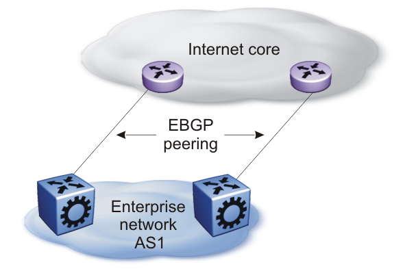
In cases where the Internet connection is single-homed, to reduce the size of the routing table, as a best practice, advertise Internet routes as the default route to the IGP.
For route scaling information, see VSP 8600 Release Notes.
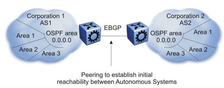
You can implement BGP so that autonomous routing domains, such as OSPF routing domains, connect. This connection allows the two different networks to begin communicating quickly over a common infrastructure, thus providing additional time to plan the IGP merger. Such a scenario is particularly effective when you need to merge two OSPF area 0.0.0.0s, as shown in the following figure.
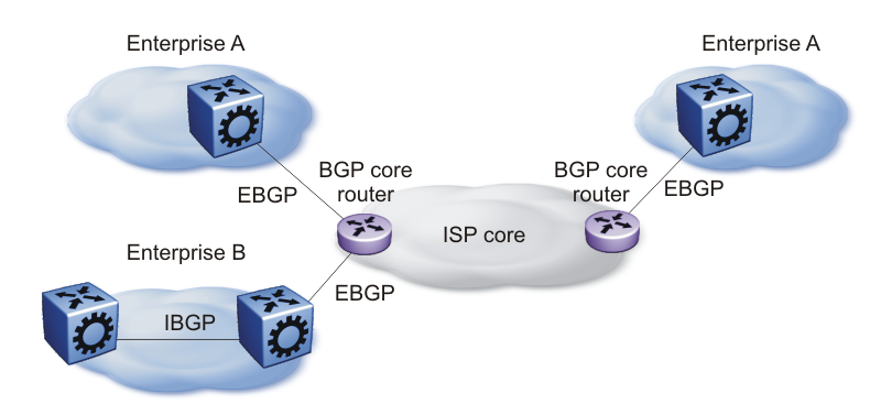
You can perform edge aggregation with multiple point of presence or edge concentrations. The switch supports 12 pairs (peering services). You can use BGP to inject dynamic routes rather than using static routes or RIP (see the following figure).
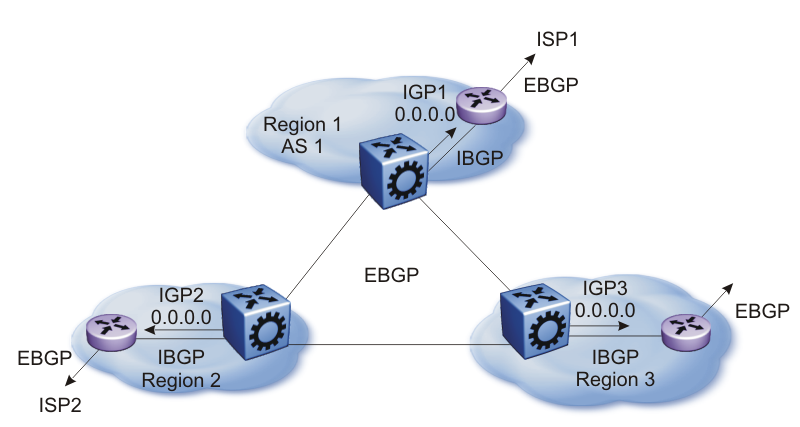
You can use the platform as a peering point between different regions or autonomous systems (AS) that belong to the same ISP. In such cases, you can define a region as an OSPF area, an AS, or a part of an AS.
You can divide the AS into multiple regions that each run different IGPs. Interconnect regions logically by using a full iBGP mesh. Each region then injects its IGP routes into iBGP and also injects a default route inside the region. For destinations that do not belong to the region, each region defaults to the BGP border router.
Use the community parameter to differentiate between regions. To provide Internet connectivity, this scenario requires you to make your Internet connections part of the central iBGP mesh (see the following figure).
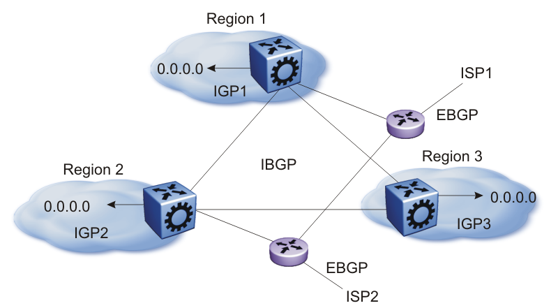
In the preceding figure, consider the following:
The AS is divided into three regions that each run different and independent IGPs.
Regions logically interconnect by using a full-mesh iBGP, which also provides Internet connectivity.
Internal non-BGP routers in each region default to the BGP border router, which contains all routes.
If the destination belongs to another region, the traffic is directed to that region; otherwise, the traffic is sent to the Internet connections according to BGP policies.
To configure multiple policies between regions, represent each region as a separate AS. Implement eBGP between autonomous systems, and implement iBGP within each AS. In such instances, each AS injects its IGP routes into BGP, where they are propagated to all other regions and the Internet.
The following figure shows the use of eBGP to join several autonomous systems.
You can obtain AS numbers from the Inter-Network Information Center (NIC) or use private AS numbers. If you use private AS numbers, be sure to design your Internet connectivity carefully. For example, you can introduce a central, well-known AS to provide interconnections between all private autonomous systems and the Internet. Before it propagates the BGP updates, this central AS strips the private AS numbers to prevent them from leaking to providers.
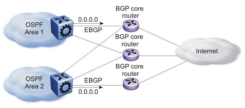
The following figure illustrates a design scenario in which you use multiple OSPF regions to enable peering with the Internet.
The following list provides rules related to BGP peers:
Only metric (=MED) attribute is applied to the output policy if its BGP peer is IBGP
metric (=MED) and community attributes are applied to output policy if its BGP peer is EBGP
To influence EBGP and IBGP peers with all applicable BGP attributes, configure route-map as an option to neighbor command, for example, neighbor 192.0.2.2 out-route-map policy1
When you configure the attribute-map with the aggregate command, community, metric, AS Path, and next-hop attributes are set, while the origin attribute is not set.
In a BGP session that is established with IPv4 and IPv6 capability, disabling or enabling IPv6 forwarding results in BGP session flapping due to capability negotiation. The flapping session in turn affects the IPv4 routing through BGP and the BGP session gets terminated. Ultimately, a capability negotiation takes place to re-establish the IPv4 and IPv6 capable session.