The following diagrams illustrate the components on the front panels of the switches. For more information on hardware, see VSP 7400 Series Switches: Hardware Installation Guide.
The following figure illustrates the components on the front panel of the VSP 7432CQ. Slot 1 is used for all of the ports.
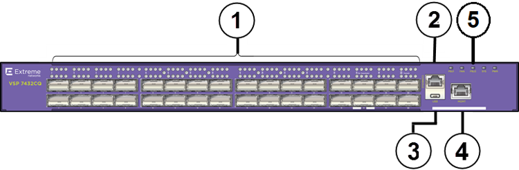
32 100-Gigabit QSFP28/QSFP+ ports each with 4 LEDs — the top row of LEDs is for the top port and the lower row of LEDs is for the lower port.
RJ-45 console port.
USB port.
OOB Management port — LinkSpeed LED on the left and Activity LED on the right.
LEDs for system power, power supply units (PSU1 and PSU2), fan modules, and system.
The VSP 7432CQ supports two internal Extreme Integrated Application Hosting (IAH) ports labeled as Insight ports, 1/s1 and 1/s2, used by IAH virtual machines. For conceptual information see Extreme Integrated Application Hosting. For configuration instructions to use internal IAH ports, see Virtual Services Configuration using CLI and Virtual Services Configuration using EDM.
The following figure illustrates the components on the front panel of the VSP 7400-48Y. Slot 1 is used for all of the ports.
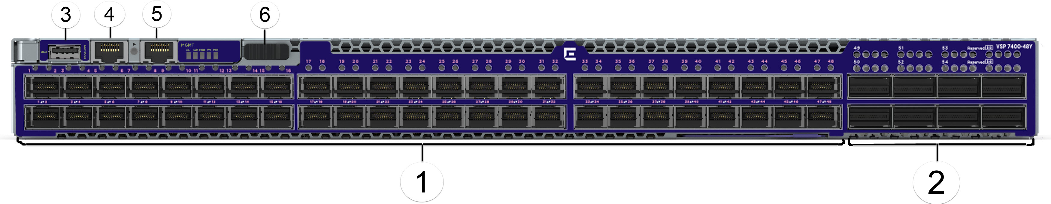
48 25-Gigabit SFP28 ports.
8 100-Gigabit QSFP28/QSFP+ ports each with 4 LEDs.
USB port.
RJ-45 console port.
OOB Management RJ-45 port — A single LinkSpeed and Activity LED on the left.
LEDs for system power, power supply units (PSU1 and PSU2), fan modules, and system are to the right of the management port.
Management Set sliding button.
The VSP 7400-48Y supports one internal IAH port, 1/s1, used by IAH virtual machines. For conceptual information see Extreme Integrated Application Hosting. For configuration instructions to use internal IAH ports, see Virtual Services Configuration using CLI and Virtual Services Configuration using EDM.