VRRP provides another layer of resiliency to your network design by providing default gateway redundancy for end users. If a VRRP-enabled router that connects to the default gateway fails, failover to the VRRP backup router ensures no interruption for end users who attempt to route from their local subnet.
Only the VRRP Master router forwards traffic for a given subnet. The backup VRRP router does not route traffic destined for the default gateway.
To enable both VRRP switches to route traffic, the switch software has an extension to VRRP, the BackupMaster, that creates an active-active environment for routing. If you enable BackupMaster on the backup router, the backup router no longer switches traffic to the VRRP Master. Instead the BackupMaster routes all traffic received on the BackupMaster IP interface according to the switch routing table.
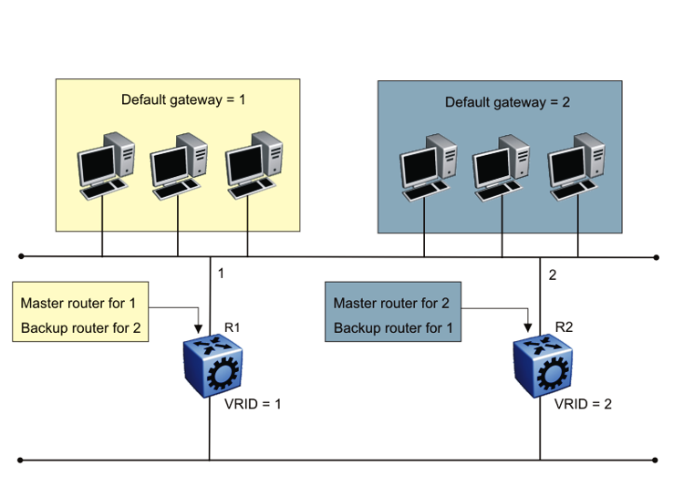
Stagger VRRP instances on a network or subnet basis. The following figure shows the VRRP Masters and BackupMasters for two subnets. For more information about how to configure VRRP using the Command Line Interface (CLI) and Enterprise Device Manager (EDM), see VRRP Configuration Using the CLI and VRRP configuration using EDM.
The VRRP BackupMaster uses the VRRP standardized backup switch state machine. Thus, VRRP BackupMaster is compatible with standard VRRP.
Use the following best practices to implement VRRP:
Do not configure the virtual address as a physical interface that is used on the routing switches. Instead, use a third address, for example:
Interface IP address of VLAN A on Switch 1 = x.x.x.2
Interface IP address of VLAN A on Switch 2 = x.x.x.3
Virtual IP address of VLAN A = x.x.x.1

Note
The switch software does not support a VRRP virtual IP address that is the same as the local physical address of the device.
Configure the VRRP holddown timer with enough time that the Interior Gateway Protocol (IGP) routing protocol has time to update the routing table. In some cases, configuring the VRRP holddown timer to a minimum of 1.5 times the IGP convergence time is sufficient. For OSPF, as a best practice, use a value of 90 seconds if you use the default OSPF timers.
Implement VRRP BackupMaster for an active-active configuration (BackupMaster works across multiple switches that participate in the same VRRP domain).
Configure VRRP priority as 200 to configure VRRP Master.
Stagger VRRP Masters between switches in the core to balance the load between switches.
If you implement VRRP Fast, you create additional control traffic on the network and also create a greater load on the CPU. To reduce the convergence time of VRRP, the VRRP Fast feature allows the modification of VRRP timers to achieve subsecond failover of VRRP. Without VRRP Fast, normal convergence time is approximately 3 seconds.
Do not use VRRP BackupMaster and critical IP at the same time. Use one or the other.
The switch can use one of two spanning tree protocols: Rapid Spanning Tree Protocol (RSTP) and Multiple Spanning Tree Protocol (MSTP).
VRRP protects clients and servers from link or aggregation switch failures. Configure the network to limit the amount of time a link is out of service during VRRP convergence. The following figure shows two possible configurations of VRRP and spanning tree; configuration A is optimal and configuration B is not.
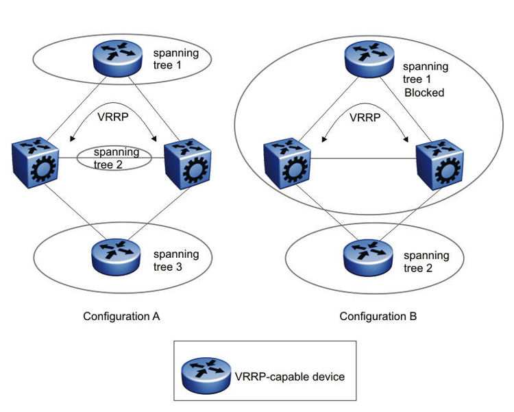
In this figure, configuration A is optimal because VRRP convergence occurs within 2 to 3 seconds. In configuration A, three spanning tree instances exist and VRRP runs on the link between the two routers. Spanning tree instance 2 exists on the link between the two routers, which separates the link between the two routers from the spanning tree instances found on the other devices. All uplinks are active.
In configuration B, VRRP convergence takes between 30 and 45 seconds because it depends on spanning tree convergence. After initial convergence, spanning tree blocks one link (an uplink), so only one uplink is used. If an error occurs on the uplink, spanning tree reconverges, which can take up to 45 seconds. After spanning tree reconvergence, VRRP can take a few more seconds to fail over.