Split MultiLink Trunking (SMLT) is an option that improves Layer 2 and Layer 3 resiliency. The following sections discuss SMLT in more detail.
Split MultiLink Trunking is an option that improves Layer 2 (bridged) resiliency by providing for the addition of switch failure redundancy with subsecond failover, on top of all standard MLT link failure protection and flexible bandwidth scaling functionality. Use Split MultiLink Trunking to connect a device that supports some form of link aggregation, be it a switch or a server, to two distinct separate SMLT endpoints or switches. These SMLT devices form a virtualized Switch Cluster through the SPBM cloud and are referred to as a Virtual Inter-Switch Trunk (vIST) Core Switch pair.
Switch Clusters are always formed as a pair, but you can combine pairs of clusters in either a square or full-mesh fashion to increase the size and port density of the Switch Cluster. If you configure SMLT in a Layer 3 or routed topology, the configuration is referenced as Routed SMLT (RSMLT).
For information about Routed SMLT, see RSMLT.
You can form SMLT connections through single links from the Switch Cluster to the edge connection, standard MLTs, or MLTs with LACP. Optionally, SMLT links can have VLACP enabled as well. You can mix these various link connections. Within the same Switch Cluster, you can configure both SMLT and RSMLT to allow a mixture of both Layer 2 and Layer 3 VLANs.
Split MultiLink Trunking networks do not need to use RSTP or MSTP to enable loop-free triangle topologies because SMLT inherently avoids loops due to its superior enhanced link aggregation protocol. The loop-free link is accomplished by having two aggregation switches, displays it as a single device to edge switches, which dual-home to the aggregation switches. The aggregation switches interconnect using a Virtual Inter-Switch trunk (vIST), exchanging addressing and state information (permitting rapid fault detection and forwarding path modification). Split MultiLink Trunking is designed for Layer 2 network connectivity, but you can configure in Layer 3 networks by working with VRRP or RSMLT Layer 2 edge.
SMLT eliminates all single points of failure and creates multiple paths from all user access switches to the network core. In case of failure, SMLT recovers as quickly as possible using all capacity. SMLT provides a transparent and interoperable solution that requires no modification on the part of the majority of existing user access devices.
SMLT improves the reliability of Layer 2 networks that operate between user access switches and the network center aggregation switch by providing:
load sharing among all links
fast failover in case of link failure
elimination of single points of failure
fast recovery in case of node failure
transparent and interoperable solutions
removal of MSTP and RSTP convergence issues
Networks designed to have user access switches dual-home to two aggregation switches, and have VLANs spanning two or more user access switches, experience the following design constraints:
no load sharing exists over redundant links
network convergence is slow in case of failure
With the introduction of SMLT, all dual-home Layer 2 frame-switched network devices with dual homes are no longer dependent on the MSTP or RSTP for loop detection. A properly designed SMLT network inherently does not have logical loops.
SMLT solves the spanning tree problem by combining two aggregation switches into one logical MLT entity, thus making it transparent to all types of edge switches. In the process, it provides quick convergence, while load sharing across all available trunks.
If you use STP mode on a switch that is in an SMLT configuration, you can experience traffic loss for 30 seconds if you change the port membership of the MLT, even if the port is in a down state. The traffic loss is because the convergence time for STP is 30 seconds. Use MSTP or RSTP on all switches in SMLT configurations.
The following are the three generic topologies in which you can deploy SMLT, depending on the resiliency and redundancy required:
a triangle topology
a square topology
a full-mesh topology
The following illustration shows an SMLT configuration with a pair of switches as aggregation systems (E and F) and four separate switches as user access switches (A, B, C, and D).

Note
In the following figure, the pair of aggregation switches (E and F) are connected by a Virtual Inter-Switch Trunk (vIST). This means that although the system displays these two switches to be directly connected, they could be anywhere within the SPBM cloud.
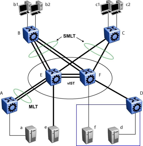
You must connect SMLT aggregation switches through vIST. For example, user access switches B and C connect to the aggregation systems through multilink trunks split between the two aggregation systems. As shown above, the implementation of SMLT only requires two SMLT-capable aggregation switches.
Aggregation switches use vIST to do the following:
Confirm that they are alive and exchange MAC address forwarding tables.
Send traffic between single switches attached to the aggregation switches.
Serve as a backup if one SMLT link fails.
Because SMLT requires vIST, use multiple links on vIST to ensure reliability and high availability. Use Gigabit Ethernet links for vIST connectivity to provide enough bandwidth for potential cross traffic.
For more information about vIST, see Virtual Inter-Switch Trunk (vIST).
A vIST multilink trunk must contain at least two physical ports.
The figure above includes end stations that connect to each of the switches. In this example, a, b1, b2, c1, c2, and d are clients and printers, while e and f are servers and routers.
User access switches B and C can use a method to determine which link of the multilink trunk connections to use to forward a packet, as long as the same link is used for a Source Address and Destination Address (SA/DA) pair. The packet is routed correctly regardless of whether B or C knows the DA. SMLT aggregation switches always send traffic directly to a user access switch, and only use vIST for traffic that they cannot forward in another, more direct way.
Traffic flow in an SMLT environment adheres to the following rules:
If a packet is received from a vIST trunk port, it is not forwarded to an active SMLT group in order to prevent network loops.
After a packet is received, the system performs a look-up on the forwarding database. If an entry exists, and if the entry was learned locally from the SMLT or through the vIST as a remote SMLT, it is forwarded to the local port (the packet must not be sent to the vIST for forwarding unless there is no local connection). Unknown and Broadcast packets flood out all ports that are members of this VLAN.
For load sharing purposes in an SMLT configuration, the switch obeys the MLT traffic distribution algorithm.
The following traffic flow examples are based on the figure above.
Assuming a and b1/b2 are communicating through Layer 2, traffic flows from A to switch E and is forwarded over its direct link to B. Traffic coming from b1 or b2 to a is sent by B on one of its multilink trunk ports.
B can send traffic from b1 to a on the link to switch E, and traffic from b2 to a on the link to F. In the case of traffic from b1, switch E forwards the traffic directly to switch A, while traffic from b2, which arrived at F, is forwarded across the vIST to E and then to A.
Traffic from b1/b2 to c1/c2 is always sent by switch B through its multilink trunk to the core. No matter at which switch E or F arrives at, it is sent directly to C through the local link.
Traffic from a to d (and d to a) is forwarded across vIST because it is the shortest path. The link is treated as a standard link; SMLT and vIST parameters are not considered.
Traffic from f to c1/c2 is sent out directly from F. Return traffic from c1/c2 passes through one active VRRP Master for each IP subnet. The traffic is passed across vIST if switch C sends it to E.
In an SMLT environment, the two aggregation switches share the same forwarding database by exchanging forwarding entries using the vIST. The entry for 00:E0:7B:B3:04:00 is shown on switch C as an entry learned on MLT-1, but because SMLT Remote is true, this entry was actually learned from switch B. On B, that same entry is shown as directly learned through MLT-1 because SMLT Remote is false.
The following illustration shows the network topology.

After a packet arrives at switch C destined for 00:E0:7B:B3:04:00, if the SMLT Remote status is true, the switch tries to send the packet to MLT-1 rather than through vIST. Traffic rarely traverses vIST unless there is a failure. If this same packet arrives at B, it is then forwarded to MLT-1 on the local ports.
The switch fully supports IEEE 802.3ad LACP on MLTs and on a pair of SMLT systems.
With LACP the switch provides a standardized external link aggregation interface to third-party vendor IEEE 802.3ad implementations. This protocol extension provides dynamic link aggregation mechanisms. Only dual-home devices benefit from this enhancement.
Advantages of this protocol extension include the following:
MLT peers and SMLT client devices can be both network switches and a type of server or workstation that supports link bundling through IEEE 802.3ad.
Single link and multilink trunk solutions support dual-home connectivity for attached devices, so that you can build dual-home server farm solutions.
SMLT/IEEE link aggregation interaction supports all known SMLT scenarios in which an IEEE 802.3ad SMLT pair connects to SMLT clients, or in which two IEEE 802.3ad SMLT pairs connect to each other in a square or full-mesh topology.
Some of the unsupported SMLT/LACP scenarios include the following factors, which lead to failure:
Incorrect port connections.
Mismatched MLT IDs assigned to SMLT client. SMLT switches can detect if MLT IDs are not consistent. The SMLT aggregation switch, which has the lower IP address, does not allow the SMLT port to become a member of the aggregation thereby avoiding misconfigurations.
The SMLT client switch does not have automatic aggregation enabled (LACP disabled). SMLT aggregation switches can detect that aggregation is not enabled on the SMLT client, thus no automatic link aggregation is established until the configuration is resolved.
Use Virtual Router Redundancy Protocol (VRRP) to have one active primary router for each IP subnet, with all other network VRRP interfaces operating in backup mode.
The VRRP has only one active routing interface enabled. Users that access switches aggregated into two SMLT switches send their shared traffic load (based on source and destination MAC or IP addresses) on all uplinks towards the SMLT aggregation switches.
Note
A VRRP virtual IP address must not be the same as the VLAN IP address of the device.
The VRRP is less efficient if you use it with SMLT. All other interfaces are in backup (standby) mode. In this case, all traffic is forwarded over the vIST link towards the primary VRRP switch. All traffic that arrives at the VRRP backup interface is forwarded, so there is not enough bandwidth on the vIST link to carry all the aggregated riser traffic. However, an enhancement to VRRP overcomes this issue by ensuring that the vIST trunk is not used in such a case for primary data forwarding.
The VRRP BackupMaster acts as an IP router for packets destined for the logical VRRP IP address. The system directly routes all traffic to the destined subnetwork and not through Layer 2 switches to the VRRP master. This avoids a potential limitation in the available vIST bandwidth.
To avoid potential frame duplication problems, you can only use the VRRP BackupMaster feature for SMLT on interfaces that you configure for SMLT. You cannot use VRRP BackupMaster with hubs to avoid frame duplication or on brouter or VLAN interfaces.
If you use an SMLT with routing on SMLT aggregation switches, use VRRP for default gateway redundancy. In a VRRP environment, one switch is active and the other is a backup. In an SMLT environment, you can enable the VRRP BackupMaster and use an active-active concept. The VRRP BackupMaster router routes traffic that is received on the SMLT VLAN and avoids traffic flow across the vIST. This provides true load-sharing abilities.
Follow these guidelines if you use VRRP BackupMaster with SMLT:
The VRRP virtual IP address and the VLAN IP address cannot be the same.
Configure the hold-down timer for VRRP to a value that is approximately one hundred and fifty percent of the Interior Gateway Protocol (IGP) convergence time to allow the IGP enough time to reconverge following a failure. For example, if OSPF takes 40 seconds to reconverge, configure the hold-down timer to 60 seconds.
Enable hold-down times on both VRRP sides (Master and BackupMaster).
You can use Simple Loop Prevention Protocol (SLPP) to prevent loops in an SMLT network. SLPP focuses on SMLT networks but works with other configurations. Always use SLPP in an SMLT environment.
Note
If SLPP is used in a vIST environment, it must be enabled on both the vIST peers. Because, when an SLPP packet of a vIST peer is looped through UNI ports to the other device, that device will shut down its UNI port due to receiving SLPP packets from its peer. A device‘s own SLPP packets will go over a vIST connection but will not be forwarded by its vIST peer back onto its UNI ports.
For square and full-mesh configurations that use a routed core, create a separate core VLAN. Enable SLPP on the core VLAN and the square or full mesh links between switch clusters. This configuration detects loops created in the core and loops at the edge do not affect core ports. If you use RSMLT between the switch clusters, enable SLPP on the RSMLT VLAN. Because you enable SLPP only on one or two VLANs in the core, changing the RX threshold values will not be necessary.
The SLPP design is to shut down the port where the SLPP packets originate or to shut down the vIST peer switch port, after the counter reaches the threshold. A loop can still occur after ports are shut down. SLPP can shut down all SMLT ports on a triangle SMLT topology, which results in isolating the edge switch.