SPBM supports Layer 2 VSN functionality where customer VLANs (C-VLANs) are bridged over the SPBM core infrastructure.
At the Backbone Edge Bridges (BEBs), customer VLANs (C-VLAN) are mapped to I-SIDs based on the local service provisioning. Outgoing frames are encapsulated in a MAC-in-MAC header, and then forwarded across the core to the far-end BEB, which strips off the encapsulation and forwards the frame to the destination network based on the I-SID-to-C-VLAN provisioning.
In the backbone VLAN (B-VLAN), Backbone Core Bridges (BCBs) forward the encapsulated traffic based on the BMAC-DA, using the shortest path topology learned using IS-IS.
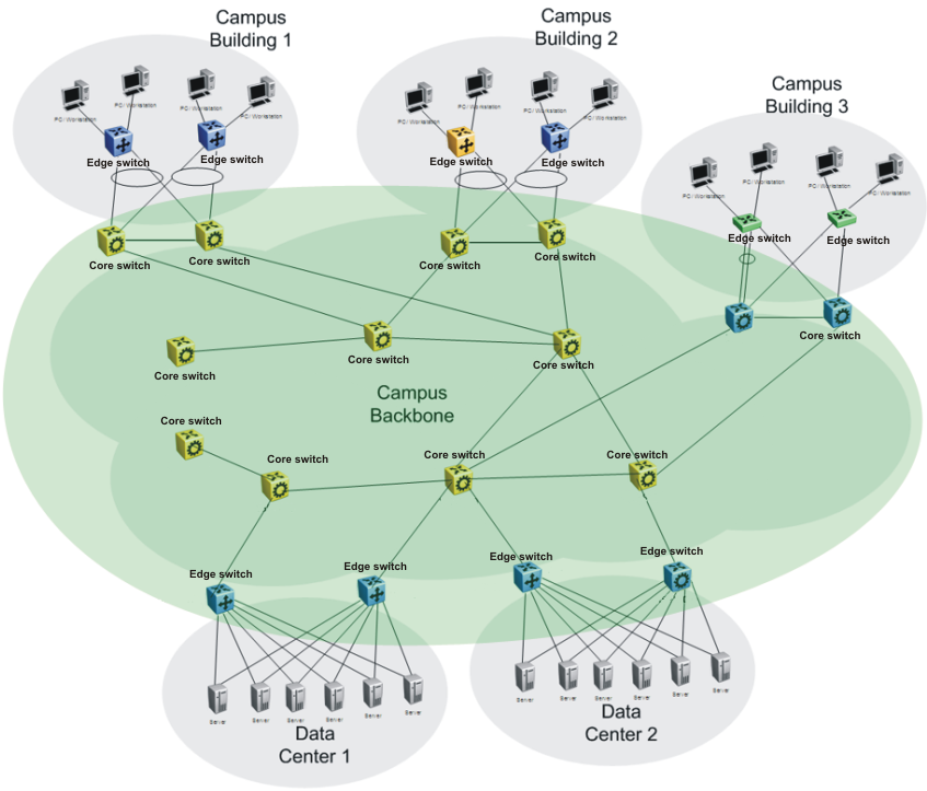
The following figure shows a sample campus SPBM Layer 2 VSN network.
One of the key advantages of the SPBM Layer 2 VSN is that network virtualization provisioning is achieved by configuring only the edge of the network (BEBs). As a result, the intrusive core provisioning that other Layer 2 virtualization technologies require is not needed when new connectivity services are added to the SPBM network. For example, when new virtual server instances are created and need their own VLAN instances, they are provisioned at the network edge only and do not need to be configured throughout the rest of the network infrastructure.
Based on its I-SID scalability, this solution can scale much higher than any 802.1Q tagging based solution. Also, due to the fact that there is no need for Spanning Tree in the core, this solution does not need any core link provisioning for normal operation.
Redundant connectivity between the C-VLAN domain and the SPBM infrastructure can be achieved by operating two SPBM switches in switch clustering (SMLT) mode. This allows the dual homing of any traditional link aggregation capable device into an SPBM network.
One major difference between these VSP switches and the ERS 8800 is how they connect to two SMLT devices.
The ERS 8800 uses an interswitch trunk (IST). The IST connects directly to two SMLT devices with a dedicated MLT and runs IS-IS over it. The dedicated MLT carries the IST control traffic and data traffic during an SMLT failover. This feature dramatically improves resiliency over other methods. However, if the dedicated MLT breaks, then there is no way to communicate between the IST peers, which causes traffic loss.
These VSP switches use a virtual IST (vIST) that eliminates this single point of failure. The vIST feature creates a virtualized IST channel in the SPBM cloud. With vIST, the IST tunnel is always up as long as there is SPBM connectivity between the vIST peers. vIST also interoperates between any two devices that support vIST, and the devices do not have to be the same type of device.
Enable SPBM and IS-IS globally.
Configure SPBM and IS-IS.
Create a VLAN (that is not used anywhere else) for each peer.
Create an I-SID that is not used anywhere else.
Configure an IP address for the vIST VLAN.
Configure an Layer 2 VSN by assigning an I-SID to the C-VLAN, which is used by the vIST.

Important
An I-SID must be assigned to every VLAN that is a member of an Layer 2 VSN.
For proper traffic flow, if an Layer 2 VSN is created on one vIST peer, it must also be created on the other vIST peer.
For Simplified vIST deployment, if a VLAN is part of an SMLT it must be configured on both the IST peers.
For information about vIST, see MultiLink Trunking and Split MultiLink Trunking.